Cirkit Designer Logo
Cirkit Designer
Your all-in-one circuit design IDE
Home / 
Component Documentation

How to Use Siemens Schütz: Examples, Pinouts, and Specs

Image of Siemens Schütz
Cirkit Designer LogoDesign with Siemens Schütz in Cirkit Designer

Introduction

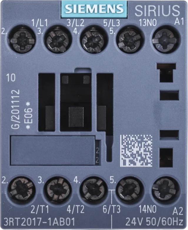
The Siemens Schütz (part number: 3RT2017-1AB01) is a high-quality contactor designed for controlling and switching high-power electrical devices. Manufactured by Siemens, this component is widely used in industrial automation, motor control, and power distribution systems. It operates as an electrically controlled switch, allowing a low-power control signal to manage high-power loads safely and efficiently.

Explore Projects Built with Siemens Schütz

Use Cirkit Designer to design, explore, and prototype these projects online. Some projects support real-time simulation. Click "Open Project" to start designing instantly!
Arduino Mega 2560 Controlled Railway Crossing with Servo Barriers and Audio Alerts
Image of Bahnübergang: A project utilizing Siemens Schütz in a practical application
This circuit features an Arduino Mega 2560 as the central controller, interfaced with a variety of components including two Servos, a DFPlayer Mini MP3 module with a Loudspeaker for audio output, a Real-Time Clock (RTC DS3231), a 3.5 TFT LCD Shield for display, and multiple pushbuttons with octocouplers for input. The circuit is designed to control a model railway crossing with signal lights (Lichtzeichenanlage), barriers (Servos), and an audio warning system (DFPlayer Mini and Loudspeaker), with the Arduino managing the logic and timing based on button inputs and the RTC. The system uses a 4 x AAA Battery Mount and a separate 3xAA Battery for power, with resistors for current limiting and signal conditioning.
Cirkit Designer LogoOpen Project in Cirkit Designer
Basic Surge Protection Circuit with Benedict Switch
Image of DC & Monitoring Box: A project utilizing Siemens Schütz in a practical application
The circuit includes a Benedict Switch connected in series with a Fuse Holder and an SPD (Surge Protection Device). The SPD is also connected to a Ground reference. This configuration suggests that the circuit is designed to control power flow, protect against overcurrent with the fuse, and guard against voltage surges with the SPD, with a safe path to ground for surge dissipation.
Cirkit Designer LogoOpen Project in Cirkit Designer
Cellular-Enabled IoT Device with Real-Time Clock and Power Management
Image of LRCM PHASE 2 BASIC: A project utilizing Siemens Schütz in a practical application
This circuit features a LilyGo-SIM7000G module for cellular communication and GPS functionality, interfaced with an RTC DS3231 for real-time clock capabilities. It includes voltage sensing through two voltage sensor modules, and uses an 8-channel opto-coupler for isolating different parts of the circuit. Power management is handled by a buck converter connected to a DC power source and batteries, with a fuse for protection and a rocker switch for on/off control. Additionally, there's an LED for indication purposes.
Cirkit Designer LogoOpen Project in Cirkit Designer
Arduino Mega 2560 Based Security System with Fingerprint Authentication and SMS Alerts
Image of Door security system: A project utilizing Siemens Schütz in a practical application
This circuit features an Arduino Mega 2560 microcontroller interfaced with a SIM800L GSM module, two fingerprint scanners, an I2C LCD display, an IR sensor, and a piezo buzzer. Power management is handled by a PowerBoost 1000 Basic Pad USB, a TP4056 charging module, and a Li-ion 18650 battery, with an option to use a Mini AC-DC 110V-230V to 5V 700mA module for direct power supply. The primary functionality appears to be a security system with GSM communication capabilities, biometric access control, and visual/audible feedback.
Cirkit Designer LogoOpen Project in Cirkit Designer

Explore Projects Built with Siemens Schütz

Use Cirkit Designer to design, explore, and prototype these projects online. Some projects support real-time simulation. Click "Open Project" to start designing instantly!
Image of Bahnübergang: A project utilizing Siemens Schütz in a practical application
Arduino Mega 2560 Controlled Railway Crossing with Servo Barriers and Audio Alerts
This circuit features an Arduino Mega 2560 as the central controller, interfaced with a variety of components including two Servos, a DFPlayer Mini MP3 module with a Loudspeaker for audio output, a Real-Time Clock (RTC DS3231), a 3.5 TFT LCD Shield for display, and multiple pushbuttons with octocouplers for input. The circuit is designed to control a model railway crossing with signal lights (Lichtzeichenanlage), barriers (Servos), and an audio warning system (DFPlayer Mini and Loudspeaker), with the Arduino managing the logic and timing based on button inputs and the RTC. The system uses a 4 x AAA Battery Mount and a separate 3xAA Battery for power, with resistors for current limiting and signal conditioning.
Cirkit Designer LogoOpen Project in Cirkit Designer
Image of DC & Monitoring Box: A project utilizing Siemens Schütz in a practical application
Basic Surge Protection Circuit with Benedict Switch
The circuit includes a Benedict Switch connected in series with a Fuse Holder and an SPD (Surge Protection Device). The SPD is also connected to a Ground reference. This configuration suggests that the circuit is designed to control power flow, protect against overcurrent with the fuse, and guard against voltage surges with the SPD, with a safe path to ground for surge dissipation.
Cirkit Designer LogoOpen Project in Cirkit Designer
Image of LRCM PHASE 2 BASIC: A project utilizing Siemens Schütz in a practical application
Cellular-Enabled IoT Device with Real-Time Clock and Power Management
This circuit features a LilyGo-SIM7000G module for cellular communication and GPS functionality, interfaced with an RTC DS3231 for real-time clock capabilities. It includes voltage sensing through two voltage sensor modules, and uses an 8-channel opto-coupler for isolating different parts of the circuit. Power management is handled by a buck converter connected to a DC power source and batteries, with a fuse for protection and a rocker switch for on/off control. Additionally, there's an LED for indication purposes.
Cirkit Designer LogoOpen Project in Cirkit Designer
Image of Door security system: A project utilizing Siemens Schütz in a practical application
Arduino Mega 2560 Based Security System with Fingerprint Authentication and SMS Alerts
This circuit features an Arduino Mega 2560 microcontroller interfaced with a SIM800L GSM module, two fingerprint scanners, an I2C LCD display, an IR sensor, and a piezo buzzer. Power management is handled by a PowerBoost 1000 Basic Pad USB, a TP4056 charging module, and a Li-ion 18650 battery, with an option to use a Mini AC-DC 110V-230V to 5V 700mA module for direct power supply. The primary functionality appears to be a security system with GSM communication capabilities, biometric access control, and visual/audible feedback.
Cirkit Designer LogoOpen Project in Cirkit Designer

Common Applications and Use Cases

  • Motor control in industrial machinery
  • Power distribution in electrical panels
  • Automation systems for switching high-current devices
  • HVAC systems for controlling compressors and fans
  • Lighting control in commercial and industrial environments

Technical Specifications

The Siemens Schütz (3RT2017-1AB01) is engineered to meet demanding industrial requirements. Below are its key technical details:

General Specifications

Parameter Value
Manufacturer Siemens
Part Number 3RT2017-1AB01
Type Contactor (Schütz)
Rated Operational Voltage 690 V AC
Rated Operational Current 9 A (AC-3)
Coil Voltage 24 V DC
Frequency 50/60 Hz
Number of Poles 3 (Three-phase)
Auxiliary Contacts 1 NO (Normally Open)
Mechanical Durability 10 million operations
Electrical Durability 1 million operations (AC-3)
Mounting Type DIN Rail or Screw Mount
Operating Temperature Range -25°C to +60°C
Dimensions (H x W x D) 77 mm x 45 mm x 86 mm
Weight Approx. 0.4 kg

Pin Configuration and Descriptions

The Siemens Schütz has terminals for both the main power circuit and the control circuit. Below is the pin configuration:

Main Power Circuit Terminals

Terminal Label Description
L1, L2, L3 Input terminals for three-phase power supply
T1, T2, T3 Output terminals to the load

Control Circuit Terminals

Terminal Label Description
A1 Positive terminal for the control coil (24 V DC)
A2 Negative terminal for the control coil (0 V)

Auxiliary Contact Terminals

Terminal Label Description
13, 14 Normally Open (NO) auxiliary contact for signaling or interlocking

Usage Instructions

How to Use the Siemens Schütz in a Circuit

  1. Power Connections:

    • Connect the three-phase power supply to the input terminals (L1, L2, L3).
    • Connect the load (e.g., motor, heater) to the output terminals (T1, T2, T3).
  2. Control Circuit:

    • Supply 24 V DC to the control coil terminals (A1 and A2). Ensure proper polarity.
    • Use a low-power control signal (e.g., from a PLC or switch) to energize the coil.
  3. Auxiliary Contacts:

    • Use the auxiliary contact terminals (13 and 14) for signaling or interlocking purposes.
  4. Mounting:

    • Mount the Schütz on a DIN rail or secure it using screws, depending on your application.

Important Considerations and Best Practices

  • Ensure the coil voltage matches the specified 24 V DC to avoid damage.
  • Verify that the load current does not exceed the rated operational current (9 A for AC-3).
  • Use proper wire gauges and tighten connections securely to prevent overheating.
  • Install the Schütz in a well-ventilated enclosure to maintain the operating temperature range.
  • For motor applications, consider using overload relays in conjunction with the Schütz for added protection.

Example: Connecting to an Arduino UNO

The Siemens Schütz can be controlled using an Arduino UNO by interfacing the control coil with a relay module or transistor circuit. Below is an example Arduino code to control the Schütz:

// Arduino code to control Siemens Schütz (3RT2017-1AB01)
// Ensure a relay module or transistor circuit is used to drive the 24 V DC coil.

const int controlPin = 7; // Pin connected to the relay module or transistor base

void setup() {
  pinMode(controlPin, OUTPUT); // Set the control pin as an output
  digitalWrite(controlPin, LOW); // Initialize the pin to LOW (Schütz OFF)
}

void loop() {
  digitalWrite(controlPin, HIGH); // Turn ON the Schütz
  delay(5000); // Keep it ON for 5 seconds
  digitalWrite(controlPin, LOW); // Turn OFF the Schütz
  delay(5000); // Keep it OFF for 5 seconds
}

Note: Use a relay module or transistor circuit to interface the Arduino with the Schütz, as the Arduino cannot directly supply the required 24 V DC for the control coil.

Troubleshooting and FAQs

Common Issues and Solutions

  1. Schütz Does Not Activate:

    • Cause: Insufficient or incorrect coil voltage.
    • Solution: Verify that the control circuit is supplying 24 V DC to the coil terminals (A1 and A2).
  2. Overheating of Terminals:

    • Cause: Loose connections or undersized wires.
    • Solution: Tighten all connections and use wires of appropriate gauge.
  3. Load Does Not Operate:

    • Cause: Faulty load or incorrect wiring.
    • Solution: Check the load and ensure proper wiring between the Schütz and the load.
  4. Auxiliary Contact Not Functioning:

    • Cause: Miswiring or damaged auxiliary contact.
    • Solution: Verify wiring and test the auxiliary contact for continuity.

FAQs

  • Q: Can the Schütz be used with a single-phase load?

    • A: Yes, connect the single-phase load to one of the poles (e.g., L1 and T1) and leave the other poles unused.
  • Q: Is the Schütz suitable for DC loads?

    • A: The 3RT2017-1AB01 is primarily designed for AC loads. For DC loads, consult Siemens for a suitable model.
  • Q: Can I use the Schütz in outdoor environments?

    • A: The Schütz should be installed in a weatherproof enclosure if used outdoors.
  • Q: How do I test the Schütz?

    • A: Apply 24 V DC to the coil terminals (A1 and A2) and check for continuity between the input and output terminals (e.g., L1 and T1).

This documentation provides a comprehensive guide to understanding, using, and troubleshooting the Siemens Schütz (3RT2017-1AB01). For further assistance, refer to the Siemens technical support team or product datasheet.