Cirkit Designer Logo
Cirkit Designer
Your all-in-one circuit design IDE
Home / 
Component Documentation

How to Use Si4463 Breakout: Examples, Pinouts, and Specs

Image of Si4463 Breakout
Cirkit Designer LogoDesign with Si4463 Breakout in Cirkit Designer

Introduction

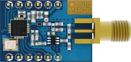
The Si4463 Breakout Board is a compact, high-performance, easy-to-use platform for the Si4463 wireless transceiver module from Silicon Labs. This module is capable of operating in the sub-GHz frequency bands and can be used to implement various wireless communication systems, including remote control systems, sensor networks, and telemetry. Its versatility makes it suitable for hobbyists, researchers, and industrial applications alike.

Explore Projects Built with Si4463 Breakout

Use Cirkit Designer to design, explore, and prototype these projects online. Some projects support real-time simulation. Click "Open Project" to start designing instantly!
Cellular-Connected ESP32-CAM with Real-Time Clock and Isolated Control
Image of LRCM PHASE 2 PRO: A project utilizing Si4463 Breakout in a practical application
This circuit integrates a LilyGo-SIM7000G module with an RTC DS3231 for timekeeping, interfaced via I2C (SCL and SDA lines). An 8-Channel OPTO-COUPLER is used to isolate and interface external signals with the LilyGo-SIM7000G's GPIOs. Power is managed by a Buck converter, which steps down voltage from a DC Power Source to supply the ESP32-CAM and LilyGo-SIM7000G modules, as well as the OPTO-COUPLER.
Cirkit Designer LogoOpen Project in Cirkit Designer
Cellular-Enabled IoT Device with Real-Time Clock and Power Management
Image of LRCM PHASE 2 BASIC: A project utilizing Si4463 Breakout in a practical application
This circuit features a LilyGo-SIM7000G module for cellular communication and GPS functionality, interfaced with an RTC DS3231 for real-time clock capabilities. It includes voltage sensing through two voltage sensor modules, and uses an 8-channel opto-coupler for isolating different parts of the circuit. Power management is handled by a buck converter connected to a DC power source and batteries, with a fuse for protection and a rocker switch for on/off control. Additionally, there's an LED for indication purposes.
Cirkit Designer LogoOpen Project in Cirkit Designer
ESP32-Powered Obstacle Avoidance Robot with IR and Ultrasonic Sensors
Image of projcememek: A project utilizing Si4463 Breakout in a practical application
This circuit features a 18650 Li-Ion battery connected to a TP4056 charging module, which in turn is connected to an MT3608 boost converter to step up the voltage. The output of the MT3608 powers an ESP32 microcontroller, a TCRT 5000 IR sensor, an HC-SR04 ultrasonic sensor, and an MG996R servo motor. The ESP32 is configured to control the servo motor via GPIO 27 and to receive input signals from the IR sensor and ultrasonic sensor through GPIO 14 and GPIO 13, respectively.
Cirkit Designer LogoOpen Project in Cirkit Designer
Battery-Powered Arduino UNO and ESP-8266 Smart Controller with LCD and RTC
Image of Ogie Diagram: A project utilizing Si4463 Breakout in a practical application
This circuit is a power management and control system that uses a 12V power supply and a 18650 Li-ion battery pack to provide a stable 5V output through a step-down buck converter. It includes an Arduino UNO, an ESP-8266 controller, a DS1307 RTC module, and a 20x4 I2C LCD display for monitoring and control purposes. The ULN2003A breakout board is used for driving higher current loads.
Cirkit Designer LogoOpen Project in Cirkit Designer

Explore Projects Built with Si4463 Breakout

Use Cirkit Designer to design, explore, and prototype these projects online. Some projects support real-time simulation. Click "Open Project" to start designing instantly!
Image of LRCM PHASE 2 PRO: A project utilizing Si4463 Breakout in a practical application
Cellular-Connected ESP32-CAM with Real-Time Clock and Isolated Control
This circuit integrates a LilyGo-SIM7000G module with an RTC DS3231 for timekeeping, interfaced via I2C (SCL and SDA lines). An 8-Channel OPTO-COUPLER is used to isolate and interface external signals with the LilyGo-SIM7000G's GPIOs. Power is managed by a Buck converter, which steps down voltage from a DC Power Source to supply the ESP32-CAM and LilyGo-SIM7000G modules, as well as the OPTO-COUPLER.
Cirkit Designer LogoOpen Project in Cirkit Designer
Image of LRCM PHASE 2 BASIC: A project utilizing Si4463 Breakout in a practical application
Cellular-Enabled IoT Device with Real-Time Clock and Power Management
This circuit features a LilyGo-SIM7000G module for cellular communication and GPS functionality, interfaced with an RTC DS3231 for real-time clock capabilities. It includes voltage sensing through two voltage sensor modules, and uses an 8-channel opto-coupler for isolating different parts of the circuit. Power management is handled by a buck converter connected to a DC power source and batteries, with a fuse for protection and a rocker switch for on/off control. Additionally, there's an LED for indication purposes.
Cirkit Designer LogoOpen Project in Cirkit Designer
Image of projcememek: A project utilizing Si4463 Breakout in a practical application
ESP32-Powered Obstacle Avoidance Robot with IR and Ultrasonic Sensors
This circuit features a 18650 Li-Ion battery connected to a TP4056 charging module, which in turn is connected to an MT3608 boost converter to step up the voltage. The output of the MT3608 powers an ESP32 microcontroller, a TCRT 5000 IR sensor, an HC-SR04 ultrasonic sensor, and an MG996R servo motor. The ESP32 is configured to control the servo motor via GPIO 27 and to receive input signals from the IR sensor and ultrasonic sensor through GPIO 14 and GPIO 13, respectively.
Cirkit Designer LogoOpen Project in Cirkit Designer
Image of Ogie Diagram: A project utilizing Si4463 Breakout in a practical application
Battery-Powered Arduino UNO and ESP-8266 Smart Controller with LCD and RTC
This circuit is a power management and control system that uses a 12V power supply and a 18650 Li-ion battery pack to provide a stable 5V output through a step-down buck converter. It includes an Arduino UNO, an ESP-8266 controller, a DS1307 RTC module, and a 20x4 I2C LCD display for monitoring and control purposes. The ULN2003A breakout board is used for driving higher current loads.
Cirkit Designer LogoOpen Project in Cirkit Designer

Common Applications and Use Cases

  • Remote controls
  • Home automation systems
  • Wireless sensor networks
  • Telemetry and data logging
  • IoT devices

Technical Specifications

The Si4463 module is a feature-rich wireless transceiver that offers adjustable output power, high sensitivity, and low power consumption. Below are the key technical specifications and pin configuration for the Si4463 Breakout Board.

Key Technical Details

  • Frequency Range: 142 to 1050 MHz
  • Modulation: FSK, GFSK, OOK
  • Output Power: Up to +20 dBm
  • Sensitivity: Down to -126 dBm
  • Data Rate: Up to 1 Mbps
  • Supply Voltage: 1.8 to 3.6 V
  • Operating Temperature: -40 to +85 °C

Pin Configuration and Descriptions

Pin Number Name Description
1 GND Ground connection
2 VCC Power supply (1.8V to 3.6V)
3 SDO Serial Data Output (SPI interface)
4 SDI Serial Data Input (SPI interface)
5 SCLK Serial Clock (SPI interface)
6 nSEL Chip Select (active low, SPI interface)
7 nIRQ Interrupt Request (active low)
8 GPIO0 General Purpose I/O (configurable)
9 GPIO1 General Purpose I/O (configurable)
10 GPIO2 General Purpose I/O (configurable)

Usage Instructions

How to Use the Component in a Circuit

  1. Power Supply: Connect the VCC pin to a clean and regulated power supply between 1.8V and 3.6V. Ensure that the GND pin is connected to the common ground of your system.
  2. SPI Interface: Connect the SDI, SDO, SCLK, and nSEL pins to the corresponding SPI pins on your microcontroller.
  3. Interrupts: The nIRQ pin can be connected to an interrupt-capable GPIO pin on your microcontroller to handle events such as packet reception or transmission completion.
  4. GPIO Pins: The GPIO0, GPIO1, and GPIO2 pins can be configured for various functions such as status indication, external control, or additional interfaces.

Important Considerations and Best Practices

  • Use decoupling capacitors close to the VCC and GND pins to filter out power supply noise.
  • Ensure that the antenna is properly matched to the module for optimal range and performance.
  • Avoid running high-speed digital lines or noisy power lines close to the antenna or RF traces.
  • Follow the guidelines provided by Silicon Labs for PCB layout to minimize interference and maximize range.

Troubleshooting and FAQs

Common Issues Users Might Face

  • No Communication: Ensure that the SPI interface is correctly configured and that the correct frequency, modulation, and power settings are used.
  • Low Range: Check the antenna design and connections. Ensure that there is no interference from other electronic devices.
  • Intermittent Operation: Verify the power supply stability and check for proper decoupling.

Solutions and Tips for Troubleshooting

  • Double-check wiring and solder joints for any loose connections or shorts.
  • Use an oscilloscope to verify the SPI communication and check for proper signal integrity.
  • Consult the Si4463 datasheet for detailed configuration options and operational modes.

FAQs

Q: Can the Si4463 Breakout Board be used with an Arduino UNO?

A: Yes, the Si4463 can be interfaced with an Arduino UNO using the SPI interface and appropriate level shifting if necessary.

Q: What is the maximum data rate supported by the Si4463?

A: The Si4463 supports data rates up to 1 Mbps.

Q: How do I configure the GPIO pins?

A: The GPIO pins can be configured using the Si4463's configuration commands, which are detailed in the Silicon Labs datasheet.

Example Arduino Code

Below is an example of how to initialize the Si4463 Breakout Board with an Arduino UNO. This code assumes that the necessary SPI library is included and that the Si4463 library or equivalent commands are available.

#include <SPI.h>

// Define the SPI interface pins
#define SS_PIN   10  // nSEL pin
#define IRQ_PIN  2   // nIRQ pin

void setup() {
  // Initialize the SPI interface
  SPI.begin();
  pinMode(SS_PIN, OUTPUT);
  digitalWrite(SS_PIN, HIGH); // Deselect the Si4463 module

  // Set up the interrupt pin
  pinMode(IRQ_PIN, INPUT);

  // Initialize the Si4463 module (pseudo code, replace with actual initialization)
  initSi4463();
}

void loop() {
  // Your main code to send or receive data
}

// Function to initialize the Si4463 module (replace with actual commands)
void initSi4463() {
  // Pseudo code to demonstrate the process
  digitalWrite(SS_PIN, LOW); // Select the Si4463 module
  // Send initialization commands via SPI
  // ...
  digitalWrite(SS_PIN, HIGH); // Deselect the Si4463 module
}

Please note that the actual initialization and usage of the Si4463 will require a series of SPI commands that are specific to the Si4463's operation. These commands can be found in the Si4463 datasheet and application notes provided by Silicon Labs. Users should refer to these documents for detailed information on configuring and using the Si4463 module.