How to Use LM2526 DC-DC Buck Converter: Examples, Pinouts, and Specs
Introduction
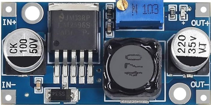
The LM2526 is a step-down voltage regulator, commonly referred to as a DC-DC buck converter. It efficiently converts a higher input voltage to a lower output voltage, making it ideal for powering devices with lower voltage requirements. This component is widely used in applications such as battery-powered systems, industrial equipment, and embedded systems where energy efficiency and stable voltage regulation are critical.
Explore Projects Built with LM2526 DC-DC Buck Converter


Explore Projects Built with LM2526 DC-DC Buck Converter
Common Applications:
- Powering microcontrollers and sensors in embedded systems
- Voltage regulation in battery-powered devices
- Industrial automation and control systems
- LED drivers and lighting systems
- Consumer electronics requiring stable low-voltage power
Technical Specifications
Key Technical Details:
- Input Voltage Range: 4.5V to 40V
- Output Voltage Range: Adjustable from 1.23V to 37V
- Output Current: Up to 3A (depending on external components and thermal conditions)
- Efficiency: Up to 90% (depending on load and input/output voltage)
- Switching Frequency: 150 kHz (fixed)
- Thermal Shutdown Protection: Yes
- Overcurrent Protection: Yes
- Package Type: TO-220 or TO-263 (varies by manufacturer)
Pin Configuration and Descriptions:
The LM2526 typically comes in a 5-pin package. Below is the pinout and description:
| Pin Number | Pin Name | Description |
|---|---|---|
| 1 | VIN | Input voltage pin. Connect to the higher input voltage (4.5V to 40V). |
| 2 | GND | Ground pin. Connect to the system ground. |
| 3 | VOUT | Output voltage pin. Provides the regulated lower voltage. |
| 4 | FB | Feedback pin. Used to set the output voltage via an external resistor divider. |
| 5 | EN | Enable pin. Used to turn the converter on or off. |
Usage Instructions
How to Use the LM2526 in a Circuit:
- Input Voltage: Connect the input voltage (VIN) to the VIN pin. Ensure the input voltage is within the specified range (4.5V to 40V).
- Output Voltage Adjustment: Use a resistor divider network connected to the FB pin to set the desired output voltage. The output voltage can be calculated using the formula: [ V_{OUT} = V_{REF} \times \left(1 + \frac{R1}{R2}\right) ] where ( V_{REF} ) is 1.23V (internal reference voltage), and ( R1 ) and ( R2 ) are the resistors in the divider.
- Output Capacitor: Connect a low-ESR capacitor (e.g., 100 µF) to the VOUT pin to stabilize the output voltage.
- Inductor Selection: Choose an inductor with appropriate current rating and inductance value to ensure efficient operation.
- Enable Pin: Connect the EN pin to VIN or a control signal to enable the converter. Pulling this pin low disables the converter.
- Ground Connection: Ensure all ground connections are properly connected to the GND pin.
Important Considerations:
- Thermal Management: Use a heatsink or ensure proper ventilation if the converter operates at high currents.
- Input Capacitor: Place a ceramic capacitor (e.g., 10 µF) close to the VIN pin to reduce input voltage ripple.
- PCB Layout: Minimize the trace length between the VIN, VOUT, and GND pins to reduce noise and improve efficiency.
- Load Regulation: Ensure the load does not exceed the maximum current rating (3A).
Example: Using LM2526 with Arduino UNO
The LM2526 can be used to power an Arduino UNO by stepping down a 12V input to 5V. Below is an example circuit and Arduino code to demonstrate its use.
Circuit:
- Connect a 12V DC power supply to the VIN pin.
- Set the output voltage to 5V using a resistor divider on the FB pin.
- Connect the VOUT pin to the Arduino UNO's 5V pin.
- Connect the GND pin to the Arduino's GND.
Arduino Code:
// Example code to blink an LED using Arduino UNO powered by LM2526
// The LM2526 provides a stable 5V to the Arduino UNO.

const int ledPin = 13; // Built-in LED pin on Arduino UNO

void setup() {
  pinMode(ledPin, OUTPUT); // Set the LED pin as an output
}

void loop() {
  digitalWrite(ledPin, HIGH); // Turn the LED on
  delay(1000);               // Wait for 1 second
  digitalWrite(ledPin, LOW);  // Turn the LED off
  delay(1000);               // Wait for 1 second
}
Troubleshooting and FAQs
Common Issues and Solutions:
No Output Voltage:
- Cause: The EN pin is not connected or is pulled low.
- Solution: Ensure the EN pin is connected to VIN or a high logic level.
Output Voltage is Incorrect:
- Cause: Incorrect resistor values in the feedback network.
- Solution: Recalculate the resistor values using the output voltage formula and verify connections.
Excessive Heat:
- Cause: High current load or insufficient cooling.
- Solution: Use a heatsink or improve ventilation. Ensure the load does not exceed 3A.
High Output Ripple:
- Cause: Insufficient output capacitance or poor PCB layout.
- Solution: Use a low-ESR capacitor and minimize trace lengths.
Converter Not Starting:
- Cause: Input voltage is below 4.5V.
- Solution: Verify the input voltage and ensure it is within the specified range.
FAQs:
Q: Can the LM2526 be used for 3.3V output?
- A: Yes, the LM2526 can be configured for 3.3V output by selecting appropriate resistor values for the feedback network.
Q: What is the maximum efficiency of the LM2526?
- A: The LM2526 can achieve up to 90% efficiency, depending on the input/output voltage and load conditions.
Q: Can I use the LM2526 without an inductor?
- A: No, an inductor is essential for the buck converter to function properly and maintain efficiency.
Q: Is the LM2526 suitable for battery-powered applications?
- A: Yes, the LM2526 is highly efficient and suitable for battery-powered systems where energy conservation is important.