
How to Use Momentary Switch: Examples, Pinouts, and Specs
 Design with Momentary Switch in Cirkit Designer
Introduction
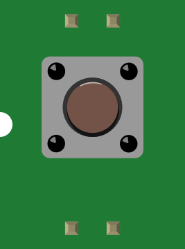
A momentary switch is a type of switch that only remains in the 'on' position while being pressed. It automatically returns to its 'off' position when released. This behavior makes it ideal for applications where a temporary connection is required. Common use cases include doorbells, keyboard keys, reset buttons, and other control interfaces where a brief activation is sufficient.
Explore Projects Built with Momentary Switch
 Open Project in Cirkit Designer
 Open Project in Cirkit Designer
 Open Project in Cirkit Designer
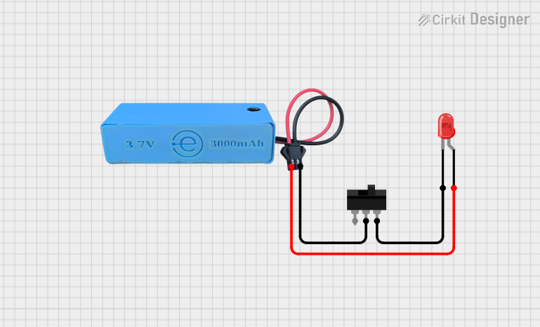 Open Project in Cirkit Designer
Explore Projects Built with Momentary Switch
Open Project in Cirkit DesignerOpen Project in Cirkit DesignerOpen Project in Cirkit DesignerOpen Project in Cirkit DesignerTechnical Specifications
- Type: Normally Open (NO) or Normally Closed (NC)
- Voltage Rating: Typically 3V to 250V (varies by model)
- Current Rating: Typically 0.5A to 5A (varies by model)
- Contact Resistance: < 50 mΩ (typical)
- Insulation Resistance: > 100 MΩ at 500V DC
- Mechanical Life: 100,000 to 1,000,000 actuations (varies by model)
- Operating Temperature: -20°C to +70°C (typical)
Pin Configuration and Descriptions
Momentary switches typically have two or more pins. Below is a general description of the pin configuration:
| Pin Name | Description |
|---|---|
| Pin 1 | One terminal of the switch. Connects to the circuit when the switch is pressed. |
| Pin 2 | The other terminal of the switch. Completes the circuit when the switch is pressed. |
For switches with additional pins (e.g., Normally Closed configurations):
| Pin Name | Description |
|---|---|
| Pin 3 | Common terminal (COM) for switches with multiple states (e.g., NO/NC). |
| Pin 4 | Normally Closed (NC) terminal. Disconnects when the switch is pressed. |
Usage Instructions
How to Use the Component in a Circuit
- Identify the Pins: Determine the pin configuration of your momentary switch (e.g., NO or NC).
- Connect the Circuit:
- For a Normally Open (NO) switch:
- Connect one pin to the positive voltage source.
- Connect the other pin to the input of the device or circuit you want to control.
- For a Normally Closed (NC) switch:
- Connect one pin to the positive voltage source.
- Connect the NC pin to the input of the device or circuit.
- For a Normally Open (NO) switch:
- Test the Switch: Press the switch to verify that it temporarily completes or interrupts the circuit.
Important Considerations and Best Practices
- Debouncing: Momentary switches can produce electrical noise or "bouncing" when pressed. Use a capacitor or software debouncing techniques to ensure stable operation.
- Current and Voltage Ratings: Ensure the switch's ratings match your circuit requirements to avoid damage.
- Mounting: Secure the switch properly to prevent mechanical stress or accidental disconnections.
- Polarity: Momentary switches are typically non-polarized, meaning they can be connected in either direction.
Example: Using a Momentary Switch with an Arduino UNO
Below is an example of how to use a momentary switch to control an LED with an Arduino UNO:
// Define pin connections
const int switchPin = 2; // Momentary switch connected to digital pin 2
const int ledPin = 13;   // LED connected to digital pin 13

void setup() {
  pinMode(switchPin, INPUT_PULLUP); // Configure switch pin as input with pull-up resistor
  pinMode(ledPin, OUTPUT);          // Configure LED pin as output
}

void loop() {
  int switchState = digitalRead(switchPin); // Read the state of the switch

  if (switchState == LOW) { // Switch is pressed (LOW due to pull-up resistor)
    digitalWrite(ledPin, HIGH); // Turn on the LED
  } else {
    digitalWrite(ledPin, LOW);  // Turn off the LED
  }
}
Notes:
- The
INPUT_PULLUPmode enables the internal pull-up resistor, simplifying the circuit. - When the switch is pressed, the pin reads
LOWbecause it is connected to ground.
Troubleshooting and FAQs
Common Issues Users Might Face
Switch Not Working:
- Cause: Incorrect wiring or loose connections.
- Solution: Double-check the pin connections and ensure they are secure.
Switch Bouncing:
- Cause: Mechanical bouncing of the switch contacts.
- Solution: Add a small capacitor (e.g., 0.1 µF) across the switch terminals or implement software debouncing.
Switch Fails to Activate the Circuit:
- Cause: Exceeding the voltage or current rating of the switch.
- Solution: Verify that the switch's ratings match your circuit requirements.
Intermittent Operation:
- Cause: Dirt or oxidation on the switch contacts.
- Solution: Clean the contacts or replace the switch if necessary.
FAQs
Q: Can I use a momentary switch to control a motor?
- A: Yes, but you may need a relay or transistor to handle the motor's current if it exceeds the switch's rating.
Q: What is the difference between Normally Open (NO) and Normally Closed (NC) switches?
- A: An NO switch remains open (disconnected) until pressed, while an NC switch remains closed (connected) until pressed.
Q: How do I debounce a momentary switch in software?
- A: Use a delay or a state-checking algorithm in your code to filter out rapid changes in the switch state.
By following this documentation, you can effectively integrate a momentary switch into your electronic projects!