Cirkit Designer Logo
Cirkit Designer
Your all-in-one circuit design IDE
Home / 
Component Documentation

How to Use TXS0108E High Speed Full Duplex Shifter 8 Way 8 Channel Logic Level Conversion Module 8-Bit 8 CH: Examples, Pinouts, and Specs

Image of TXS0108E High Speed Full Duplex Shifter 8 Way 8 Channel Logic Level Conversion Module 8-Bit 8 CH
Cirkit Designer LogoDesign with TXS0108E High Speed Full Duplex Shifter 8 Way 8 Channel Logic Level Conversion Module 8-Bit 8 CH in Cirkit Designer

Introduction

The TXS0108E by DEVMO is an 8-channel bidirectional logic level converter designed to facilitate communication between devices operating at different voltage levels. It supports high-speed data transfer and is particularly useful for interfacing 3.3V and 5V systems. This module is ideal for applications involving microcontrollers, sensors, and other peripherals that require voltage level translation.

Explore Projects Built with TXS0108E High Speed Full Duplex Shifter 8 Way 8 Channel Logic Level Conversion Module 8-Bit 8 CH

Use Cirkit Designer to design, explore, and prototype these projects online. Some projects support real-time simulation. Click "Open Project" to start designing instantly!
Wi-Fi Controlled Device Interface with Wemos D1 Mini and Logic Level Converter
Image of Toshiba AC D1 mini: A project utilizing TXS0108E High Speed Full Duplex Shifter 8 Way 8 Channel Logic Level Conversion Module 8-Bit 8 CH in a practical application
This circuit features a Wemos D1 Mini microcontroller interfaced with a Bi-Directional Logic Level Converter to facilitate communication with a 5V RX/TX module. The level converter ensures proper voltage translation between the 3.3V logic of the Wemos D1 Mini and the 5V logic of the RX/TX module.
Cirkit Designer LogoOpen Project in Cirkit Designer
Arduino Mega 2560 Controlled Motor System with I2C Communication and Hall Effect Sensing
Image of Uni1: A project utilizing TXS0108E High Speed Full Duplex Shifter 8 Way 8 Channel Logic Level Conversion Module 8-Bit 8 CH in a practical application
This is a motor control system with feedback and sensor integration. It uses an Arduino Mega 2560 to control MD03 motor drivers for DC motors, receives position and speed feedback from HEDS encoders and Hall sensors, and measures distance with SR02 ultrasonic sensors. Logic level converters ensure compatibility between different voltage levels of the components.
Cirkit Designer LogoOpen Project in Cirkit Designer
ESP32 and Logic Level Converter-Based Wi-Fi Controlled Interface
Image of Toshiba AC ESP32 devkit v1: A project utilizing TXS0108E High Speed Full Duplex Shifter 8 Way 8 Channel Logic Level Conversion Module 8-Bit 8 CH in a practical application
This circuit features an ESP32 Devkit V1 microcontroller connected to a Bi-Directional Logic Level Converter, which facilitates voltage level shifting between the ESP32 and external components. The ESP32 is powered through its VIN pin via an alligator clip cable, and the logic level converter is connected to various pins on the ESP32 to manage different voltage levels for communication.
Cirkit Designer LogoOpen Project in Cirkit Designer
Arduino UNO and Relay-Controlled RS485 Communication System
Image of Diagrama: A project utilizing TXS0108E High Speed Full Duplex Shifter 8 Way 8 Channel Logic Level Conversion Module 8-Bit 8 CH in a practical application
This circuit features an Arduino UNO microcontroller interfaced with a 4-channel relay module and a UART TTL to RS485 converter. The Arduino controls the relays via digital pins and communicates with the RS485 converter for serial communication, enabling control of external devices and communication over long distances.
Cirkit Designer LogoOpen Project in Cirkit Designer

Explore Projects Built with TXS0108E High Speed Full Duplex Shifter 8 Way 8 Channel Logic Level Conversion Module 8-Bit 8 CH

Use Cirkit Designer to design, explore, and prototype these projects online. Some projects support real-time simulation. Click "Open Project" to start designing instantly!
Image of Toshiba AC D1 mini: A project utilizing TXS0108E High Speed Full Duplex Shifter 8 Way 8 Channel Logic Level Conversion Module 8-Bit 8 CH in a practical application
Wi-Fi Controlled Device Interface with Wemos D1 Mini and Logic Level Converter
This circuit features a Wemos D1 Mini microcontroller interfaced with a Bi-Directional Logic Level Converter to facilitate communication with a 5V RX/TX module. The level converter ensures proper voltage translation between the 3.3V logic of the Wemos D1 Mini and the 5V logic of the RX/TX module.
Cirkit Designer LogoOpen Project in Cirkit Designer
Image of Uni1: A project utilizing TXS0108E High Speed Full Duplex Shifter 8 Way 8 Channel Logic Level Conversion Module 8-Bit 8 CH in a practical application
Arduino Mega 2560 Controlled Motor System with I2C Communication and Hall Effect Sensing
This is a motor control system with feedback and sensor integration. It uses an Arduino Mega 2560 to control MD03 motor drivers for DC motors, receives position and speed feedback from HEDS encoders and Hall sensors, and measures distance with SR02 ultrasonic sensors. Logic level converters ensure compatibility between different voltage levels of the components.
Cirkit Designer LogoOpen Project in Cirkit Designer
Image of Toshiba AC ESP32 devkit v1: A project utilizing TXS0108E High Speed Full Duplex Shifter 8 Way 8 Channel Logic Level Conversion Module 8-Bit 8 CH in a practical application
ESP32 and Logic Level Converter-Based Wi-Fi Controlled Interface
This circuit features an ESP32 Devkit V1 microcontroller connected to a Bi-Directional Logic Level Converter, which facilitates voltage level shifting between the ESP32 and external components. The ESP32 is powered through its VIN pin via an alligator clip cable, and the logic level converter is connected to various pins on the ESP32 to manage different voltage levels for communication.
Cirkit Designer LogoOpen Project in Cirkit Designer
Image of Diagrama: A project utilizing TXS0108E High Speed Full Duplex Shifter 8 Way 8 Channel Logic Level Conversion Module 8-Bit 8 CH in a practical application
Arduino UNO and Relay-Controlled RS485 Communication System
This circuit features an Arduino UNO microcontroller interfaced with a 4-channel relay module and a UART TTL to RS485 converter. The Arduino controls the relays via digital pins and communicates with the RS485 converter for serial communication, enabling control of external devices and communication over long distances.
Cirkit Designer LogoOpen Project in Cirkit Designer

Common Applications

  • Interfacing 3.3V microcontrollers (e.g., Arduino, ESP32, Raspberry Pi) with 5V peripherals.
  • Communication between sensors and devices operating at different voltage levels.
  • Bidirectional data transfer in I2C, SPI, UART, and GPIO applications.
  • Voltage level shifting in mixed-voltage systems.

Technical Specifications

Key Technical Details

Parameter Specification
Manufacturer DEVMO
Part Number TXS0108E
Voltage Range (VCCA) 1.2V to 3.6V
Voltage Range (VCCB) 1.65V to 5.5V
Maximum Data Rate 110 Mbps (Push-Pull), 1.2 Mbps (Open-Drain)
Channels 8 Bidirectional Channels
Operating Temperature -40°C to +85°C
Package Type Module (with TXS0108E IC)
Communication Protocols Supports I2C, SPI, UART, GPIO

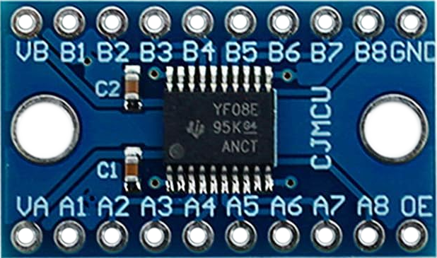
Pin Configuration and Descriptions

The TXS0108E module has 10 pins, as described in the table below:

Pin Name Direction Description
VCCA Input Voltage supply for the low-voltage side (1.2V to 3.6V).
VCCB Input Voltage supply for the high-voltage side (1.65V to 5.5V).
GND Input Ground connection (common for both voltage domains).
OE Input Output Enable pin. Active HIGH. Pull HIGH to enable the module.
A1–A8 I/O Low-voltage side data pins (1.2V to 3.6V).
B1–B8 I/O High-voltage side data pins (1.65V to 5.5V).

Usage Instructions

How to Use the TXS0108E in a Circuit

  1. Power Connections:

    • Connect the low-voltage supply (e.g., 3.3V) to the VCCA pin.
    • Connect the high-voltage supply (e.g., 5V) to the VCCB pin.
    • Connect the GND pin to the ground of your circuit.
  2. Enable the Module:

    • Pull the OE (Output Enable) pin HIGH to activate the module. If left LOW, the module will be disabled.
  3. Connect Data Lines:

    • Connect the low-voltage device's data lines to the A1–A8 pins.
    • Connect the high-voltage device's data lines to the corresponding B1–B8 pins.
    • Ensure that each channel is connected to the correct corresponding pin (e.g., A1 ↔ B1, A2 ↔ B2).
  4. Verify Voltage Levels:

    • Ensure that the voltage levels of the connected devices match the voltage ranges specified for VCCA and VCCB.

Important Considerations and Best Practices

  • Pull-Up Resistors: For open-drain communication protocols like I2C, external pull-up resistors may be required on both sides of the module.
  • Output Enable: Always ensure the OE pin is HIGH during operation. If not used, connect it to VCCA.
  • Power Supply Sequencing: Power up VCCA before VCCB to avoid potential damage to the module.
  • Data Rate: For high-speed communication, ensure the connected devices support the required data rates.

Example: Connecting TXS0108E to an Arduino UNO

Below is an example of using the TXS0108E to interface a 3.3V sensor with a 5V Arduino UNO.

Circuit Connections

  • VCCA: Connect to the 3.3V pin of the Arduino.
  • VCCB: Connect to the 5V pin of the Arduino.
  • GND: Connect to the Arduino's GND.
  • OE: Connect to the 3.3V pin of the Arduino.
  • A1: Connect to the sensor's data pin.
  • B1: Connect to the Arduino's digital pin (e.g., D2).

Arduino Code Example

// Example code for reading data from a 3.3V sensor using TXS0108E
// connected to a 5V Arduino UNO.

const int sensorPin = 2; // Arduino pin connected to B1 of TXS0108E
int sensorValue = 0;

void setup() {
  pinMode(sensorPin, INPUT); // Set sensor pin as input
  Serial.begin(9600);        // Initialize serial communication
}

void loop() {
  sensorValue = digitalRead(sensorPin); // Read sensor value
  Serial.println(sensorValue);          // Print the value to Serial Monitor
  delay(500);                           // Wait for 500ms
}

Troubleshooting and FAQs

Common Issues and Solutions

  1. Module Not Working:

    • Ensure the OE pin is pulled HIGH. Without this, the module will remain disabled.
    • Verify that VCCA and VCCB are powered correctly and within the specified voltage ranges.
  2. Data Not Transmitting:

    • Check the connections between the A and B pins. Ensure they are correctly paired (e.g., A1 ↔ B1).
    • For I2C communication, ensure pull-up resistors are present on both sides.
  3. Voltage Mismatch:

    • Confirm that the connected devices operate within the voltage ranges specified for VCCA and VCCB.
  4. Signal Distortion at High Speeds:

    • Ensure the wiring is short and properly shielded to minimize noise and signal degradation.

FAQs

Q1: Can I use the TXS0108E for SPI communication?
Yes, the TXS0108E supports SPI communication. Ensure that the SPI clock speed does not exceed the module's maximum data rate.

Q2: What happens if I leave the OE pin floating?
If the OE pin is left floating, the module may not function correctly. Always pull it HIGH to enable the module.

Q3: Can I use the TXS0108E with 1.8V devices?
Yes, the module supports 1.8V devices as long as the VCCA voltage is set within the range of 1.2V to 3.6V.

Q4: Is the TXS0108E suitable for analog signals?
No, the TXS0108E is designed for digital signals only. It is not suitable for analog signal conversion.