Introduction
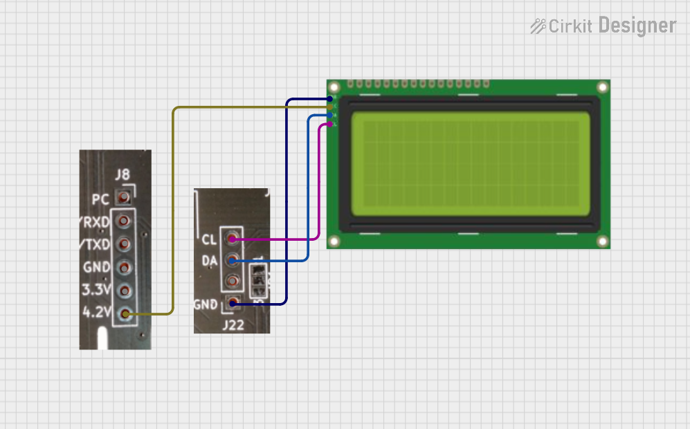
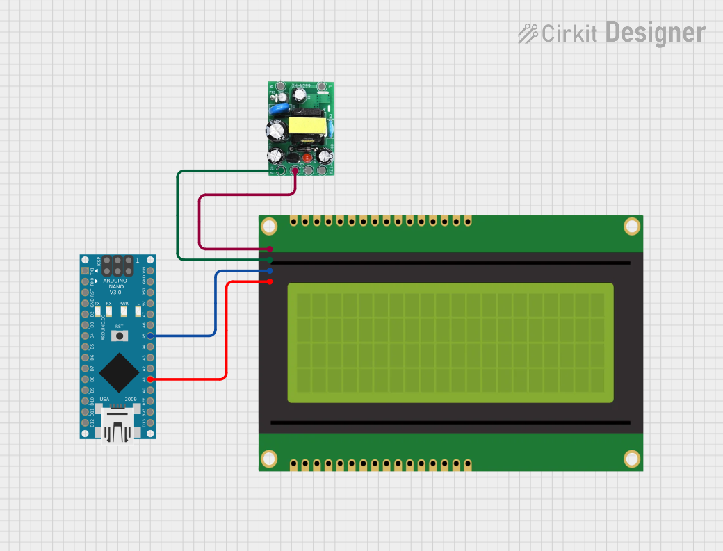
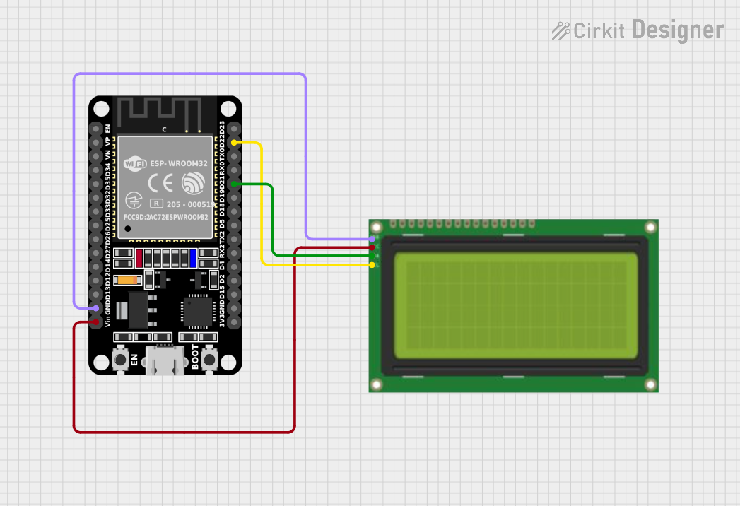
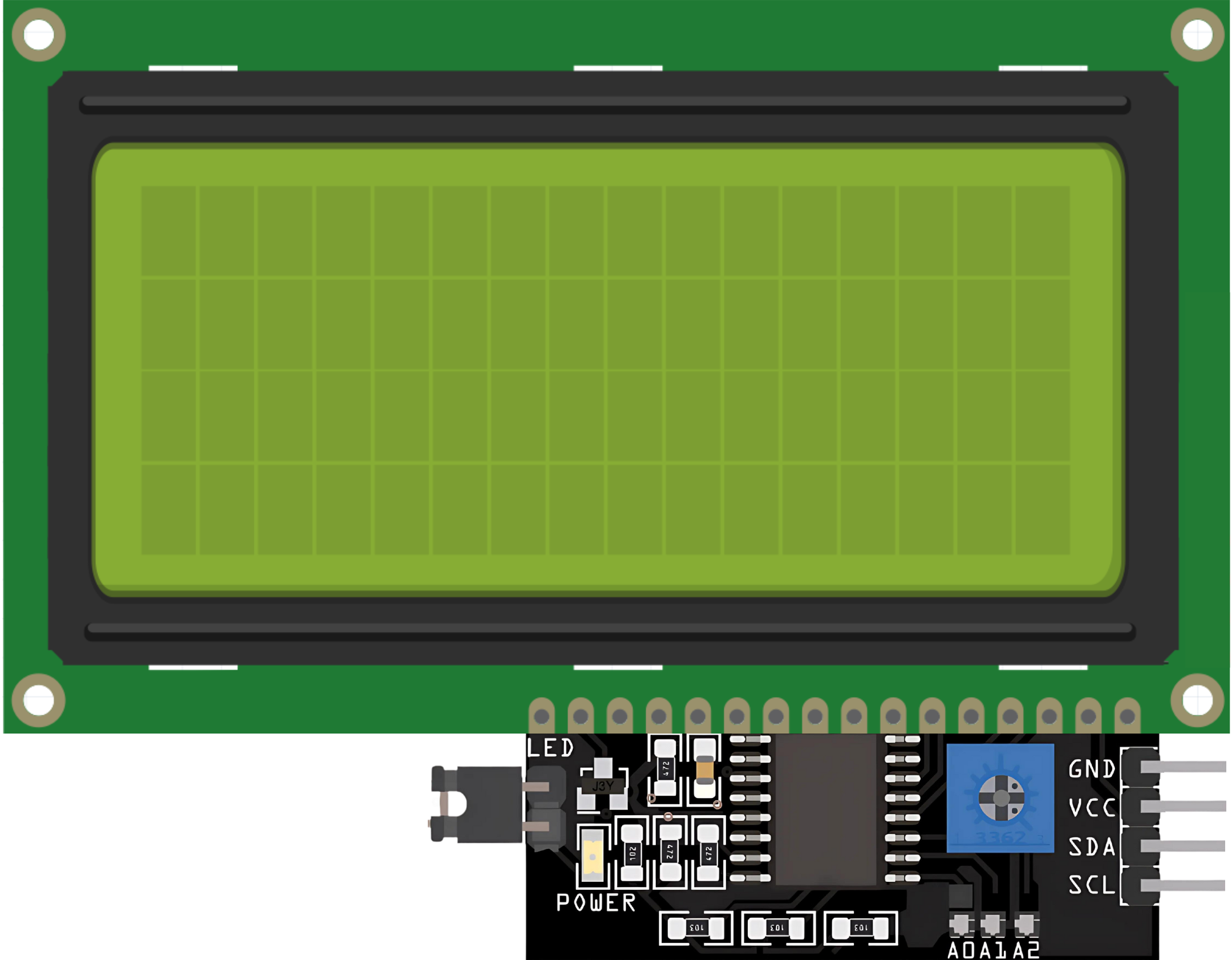
A 20x4 LCD (Liquid Crystal Display) is a type of display module that can show 20 characters per line and has 4 lines. It is commonly used in embedded systems for displaying text and simple graphics, interfacing easily with microcontrollers. This display is based on the HD44780 controller, which is widely supported by various development platforms, including Arduino.
Common Applications and Use Cases
- Embedded systems and microcontroller projects
- Industrial control panels
- Home automation systems
- Measurement and monitoring devices
- Educational and prototyping projects
Technical Specifications
Below are the key technical details of the LCD 20x4 module:
Pin Configuration and Descriptions
The LCD 20x4 module typically has 16 pins. Below is the pinout and description:
Usage Instructions
How to Use the LCD 20x4 in a Circuit
- Power Supply: Connect the VSS pin to ground and the VDD pin to a 5V power supply.
- Contrast Adjustment: Connect the VO pin to the middle terminal of a 10kΩ potentiometer. Connect the other two terminals of the potentiometer to VDD and ground.
- Control Pins: Connect the RS, RW, and E pins to digital output pins of your microcontroller.
- Data Pins: For 4-bit mode, connect D4-D7 to the microcontroller. For 8-bit mode, connect all data pins (D0-D7).
- Backlight: Connect the A (LED+) pin to 5V (through a resistor if needed) and the K (LED-) pin to ground.
- Library Support: Use an HD44780-compatible library (e.g., LiquidCrystal for Arduino) to simplify communication.
Arduino UNO Example Code
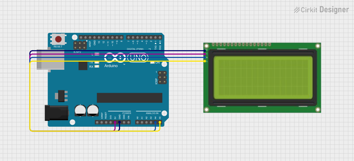
Below is an example of how to interface the LCD 20x4 with an Arduino UNO in 4-bit mode:
#include <LiquidCrystal.h>

// Initialize the library with the numbers of the interface pins
// RS -> Pin 12, E -> Pin 11, D4 -> Pin 5, D5 -> Pin 4, D6 -> Pin 3, D7 -> Pin 2
LiquidCrystal lcd(12, 11, 5, 4, 3, 2);

void setup() {
  lcd.begin(20, 4); // Set up the LCD's number of columns and rows
  lcd.print("Hello, World!"); // Print a message to the first line
}

void loop() {
  lcd.setCursor(0, 1); // Move to the first column of the second line
  lcd.print("LCD 20x4 Demo"); // Print a message to the second line
  delay(1000); // Wait for 1 second
  lcd.clear(); // Clear the display
  lcd.setCursor(0, 0); // Move back to the first line
  lcd.print("Enjoy Coding!"); // Print a new message
  delay(1000); // Wait for 1 second
}
Important Considerations and Best Practices
- Contrast Adjustment: Use a potentiometer to adjust the contrast for optimal visibility.
- Backlight Current: Ensure the backlight current does not exceed the module's rating. Use a resistor if necessary.
- 4-bit vs. 8-bit Mode: Use 4-bit mode to save microcontroller pins unless 8-bit mode is required for faster data transfer.
- Noise Reduction: Add decoupling capacitors (e.g., 0.1µF) near the power pins to reduce noise.
Troubleshooting and FAQs
Common Issues and Solutions
No Display on the Screen:
- Check the power connections (VSS and VDD).
- Adjust the contrast using the potentiometer connected to VO.
- Verify the backlight connections (A and K pins).
Random Characters or No Response:
- Ensure the RS, RW, and E pins are correctly connected to the microcontroller.
- Verify the data pin connections (D4-D7 for 4-bit mode or D0-D7 for 8-bit mode).
- Check the code for proper initialization of the LCD.
Flickering or Unstable Display:
- Add decoupling capacitors near the power supply pins.
- Ensure the Enable (E) pin is not toggling too quickly in the code.
Backlight Not Working:
- Verify the backlight connections (A and K pins).
- Check if the resistor used for the backlight is appropriate.
FAQs
Q1: Can I use the LCD 20x4 with a 3.3V microcontroller?
A1: The LCD 20x4 is designed for 5V operation. Use a level shifter or voltage divider for compatibility with 3.3V systems.
Q2: How do I display custom characters?
A2: Use the createChar() function in the LiquidCrystal library to define and display custom characters.
Q3: Can I use the LCD without a potentiometer for contrast adjustment?
A3: Yes, you can use a fixed resistor or connect VO to ground for maximum contrast, but a potentiometer provides better control.
Q4: What is the maximum viewing angle of the LCD?
A4: The viewing angle depends on the specific module but is typically around 45° to 60°. Check the datasheet for exact details.

 Open Project in Cirkit Designer