How to Use XL4016 MODULE: Examples, Pinouts, and Specs
Introduction
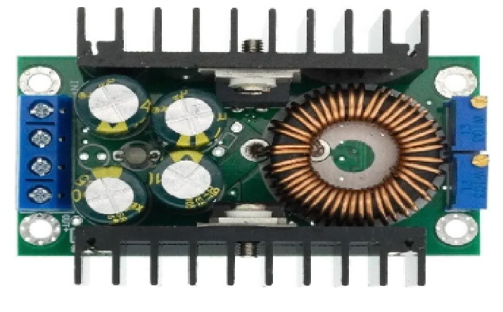
The XL4016 module is a high-power DC-DC buck converter designed to step down voltage efficiently. It is capable of converting a higher input voltage to a lower, stable output voltage with adjustable current and voltage limits. This module is widely used in applications requiring efficient power conversion, such as battery charging, LED drivers, and power supplies for electronic devices. Its high efficiency and robust design make it suitable for both hobbyist and industrial projects.
Explore Projects Built with XL4016 MODULE


Explore Projects Built with XL4016 MODULE
Common Applications:
- Battery charging (e.g., lithium-ion, lead-acid batteries)
- Adjustable power supplies for electronic circuits
- LED lighting systems
- Motor speed control
- Powering devices from higher voltage sources (e.g., solar panels, car batteries)
Technical Specifications
Key Technical Details:
- Input Voltage Range: 5V to 40V DC
- Output Voltage Range: 1.25V to 36V DC (adjustable)
- Output Current: Up to 8A (adjustable, with proper cooling)
- Power Output: Up to 200W (with adequate heat dissipation)
- Efficiency: Up to 95% (depending on input/output voltage and load)
- Switching Frequency: 180 kHz
- Voltage Regulation: ±0.5%
- Current Regulation: ±0.5%
- Protection Features: Over-temperature, over-current, and short-circuit protection
- Dimensions: Approximately 60mm x 53mm x 22mm
Pin Configuration and Descriptions:
The XL4016 module has input and output terminals for easy connection. Below is the pin configuration:
| Pin/Terminal | Description |
|---|---|
| VIN+ | Positive input voltage terminal (connect to the positive side of the power source). |
| VIN- | Negative input voltage terminal (connect to the ground of the power source). |
| VOUT+ | Positive output voltage terminal (connect to the positive side of the load). |
| VOUT- | Negative output voltage terminal (connect to the ground of the load). |
| ADJ (Potentiometer) | Used to adjust the output voltage and current. |
Usage Instructions
How to Use the XL4016 Module in a Circuit:
Connect the Input Voltage:
- Connect the positive terminal of your power source to the
VIN+pin. - Connect the ground of your power source to the
VIN-pin. - Ensure the input voltage is within the range of 5V to 40V DC.
- Connect the positive terminal of your power source to the
Connect the Load:
- Connect the positive terminal of your load to the
VOUT+pin. - Connect the ground of your load to the
VOUT-pin.
- Connect the positive terminal of your load to the
Adjust the Output Voltage:
- Use the onboard potentiometer labeled "Voltage" to adjust the output voltage.
- Turn the potentiometer clockwise to increase the voltage and counterclockwise to decrease it.
Set the Current Limit:
- Use the onboard potentiometer labeled "Current" to set the maximum output current.
- This is particularly useful for applications like battery charging to prevent overcurrent.
Power On:
- Once all connections are secure, power on the module and measure the output voltage using a multimeter to ensure it matches your requirements.
Important Considerations and Best Practices:
- Heat Dissipation: The XL4016 module can handle high currents, but it generates heat during operation. Use a heatsink or active cooling (e.g., a fan) for loads exceeding 3A.
- Input Voltage: Ensure the input voltage is at least 1.5V higher than the desired output voltage for proper operation.
- Current Limit: Always set the current limit to protect your load and the module from damage.
- Polarity: Double-check the polarity of your connections to avoid damaging the module.
- Testing: Before connecting sensitive devices, test the output voltage and current with a multimeter.
Example: Using XL4016 with Arduino UNO
The XL4016 module can be used to power an Arduino UNO from a higher voltage source. Below is an example:
- Connect a 12V DC power source to the
VIN+andVIN-terminals of the XL4016. - Adjust the output voltage to 5V using the potentiometer.
- Connect the
VOUT+terminal to the Arduino's 5V pin and theVOUT-terminal to the Arduino's GND pin.
Here is a simple Arduino code to blink an LED, powered by the XL4016 module:
// Simple LED Blink Example
// Ensure the XL4016 module is set to output 5V before connecting to Arduino.

const int ledPin = 13; // Pin connected to the onboard LED

void setup() {
  pinMode(ledPin, OUTPUT); // Set the LED pin as an output
}

void loop() {
  digitalWrite(ledPin, HIGH); // Turn the LED on
  delay(1000);                // Wait for 1 second
  digitalWrite(ledPin, LOW);  // Turn the LED off
  delay(1000);                // Wait for 1 second
}
Troubleshooting and FAQs
Common Issues and Solutions:
No Output Voltage:
- Cause: Incorrect input connections or insufficient input voltage.
- Solution: Verify the input voltage is within the 5V to 40V range and check the polarity.
Output Voltage Not Adjustable:
- Cause: Faulty potentiometer or incorrect adjustment.
- Solution: Ensure you are turning the correct potentiometer (labeled "Voltage"). If the issue persists, check for damage to the module.
Overheating:
- Cause: High current load without proper cooling.
- Solution: Add a heatsink or fan to dissipate heat effectively.
Load Not Powering On:
- Cause: Current limit set too low.
- Solution: Adjust the current limit potentiometer to match the load's requirements.
Module Damage:
- Cause: Reverse polarity or exceeding voltage/current limits.
- Solution: Always double-check connections and ensure input/output parameters are within the specified range.
FAQs:
Q: Can the XL4016 module charge a 12V lead-acid battery?
- A: Yes, set the output voltage to 14.4V (for a 12V battery) and adjust the current limit to match the battery's charging specifications.
Q: What is the maximum input voltage for the XL4016?
- A: The maximum input voltage is 40V DC. Exceeding this may damage the module.
Q: Can I use the XL4016 to power a Raspberry Pi?
- A: Yes, set the output voltage to 5V and ensure the current limit is sufficient for the Raspberry Pi's power requirements.
Q: Does the module have reverse polarity protection?
- A: No, the XL4016 does not have built-in reverse polarity protection. Always ensure correct polarity when connecting the module.
This concludes the documentation for the XL4016 module.