How to Use ILI 9486 320x480 3.5 inch: Examples, Pinouts, and Specs
Introduction
The ILI 9486 is a TFT LCD display driver designed to support a resolution of 320x480 pixels. It is widely used in embedded systems, portable devices, and other applications requiring high-quality graphical displays. This component is ideal for creating user interfaces, displaying images, or rendering dynamic content in real-time. Its compatibility with microcontrollers like Arduino makes it a popular choice for hobbyists and professionals alike.
Explore Projects Built with ILI 9486 320x480 3.5 inch


Explore Projects Built with ILI 9486 320x480 3.5 inch
Common Applications and Use Cases
- Portable devices such as handheld consoles and smart gadgets
- Embedded systems requiring graphical user interfaces
- Industrial control panels and instrumentation displays
- DIY projects and prototyping with microcontrollers
- Educational tools for learning about display technologies
Technical Specifications
Key Technical Details
| Parameter | Value |
|---|---|
| Manufacturer | ILI |
| Part ID | ILI 9486 |
| Display Type | TFT LCD |
| Resolution | 320x480 pixels |
| Color Depth | 16-bit (65,536 colors) |
| Interface | Parallel (8-bit/16-bit) or SPI |
| Operating Voltage (VDD) | 2.8V to 3.3V |
| Backlight Voltage | 3.0V to 3.6V |
| Operating Temperature | -20°C to 70°C |
| Dimensions | 3.5 inches (diagonal) |
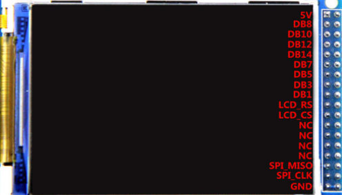
Pin Configuration and Descriptions
The ILI 9486 display module typically comes with a 40-pin interface. Below is a table describing the key pins:
| Pin Number | Pin Name | Description |
|---|---|---|
| 1-8 | DB0-DB7 | Data Bus (8-bit mode) |
| 9-16 | DB8-DB15 | Data Bus (16-bit mode, optional) |
| 17 | RS (DC) | Register Select (Command/Data selection) |
| 18 | WR | Write Signal |
| 19 | RD | Read Signal |
| 20 | CS | Chip Select (Active Low) |
| 21 | RESET | Reset Signal (Active Low) |
| 22 | IM0 | Interface Mode Selection (Parallel/SPI) |
| 23 | IM1 | Interface Mode Selection (Parallel/SPI) |
| 24 | IM2 | Interface Mode Selection (Parallel/SPI) |
| 25 | LED+ | Backlight Positive |
| 26 | LED- | Backlight Negative |
| 27-40 | GND/VDD | Ground and Power Supply |
Note: The exact pinout may vary depending on the specific module or breakout board used. Always refer to the datasheet or module documentation for precise details.
Usage Instructions
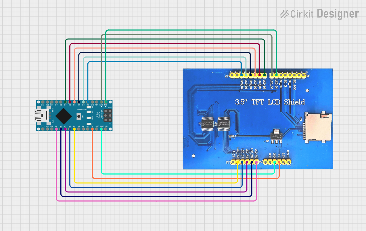
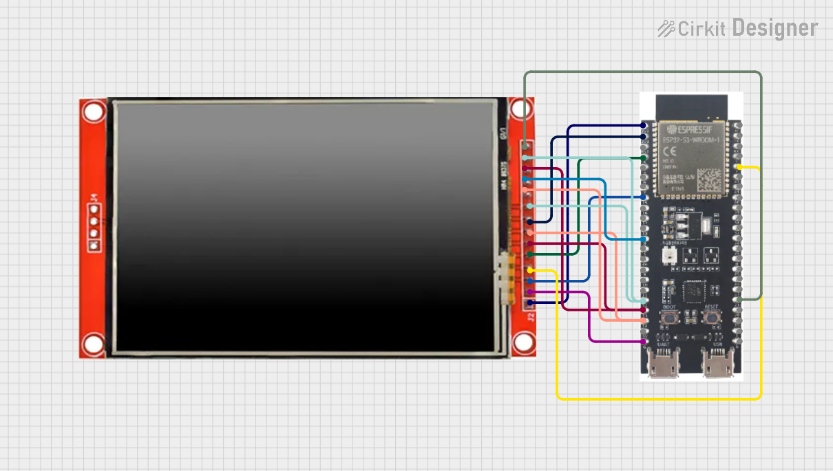
How to Use the ILI 9486 in a Circuit
- Power Supply: Connect the VDD pin to a 3.3V power source. Ensure the backlight pins (LED+ and LED-) are connected to a suitable power source (e.g., 3.3V with a current-limiting resistor).
- Interface Selection: Configure the IM0, IM1, and IM2 pins to select the desired interface mode (e.g., 8-bit parallel, 16-bit parallel, or SPI).
- Microcontroller Connection: Connect the data bus (DB0-DB15), control pins (RS, WR, RD, CS), and RESET pin to the corresponding GPIO pins of your microcontroller.
- Initialization: Use the appropriate initialization sequence to configure the display. This typically involves sending a series of commands to set the resolution, color depth, and other parameters.
- Data Transmission: Send pixel data or commands to the display using the selected interface. For example, in parallel mode, write data to the data bus and toggle the WR pin.
Important Considerations and Best Practices
- Voltage Levels: Ensure all signal lines are within the voltage range specified in the datasheet. Use level shifters if your microcontroller operates at 5V.
- Backlight Control: Use a current-limiting resistor or a dedicated LED driver circuit to prevent damage to the backlight.
- Initialization Sequence: Follow the initialization sequence provided in the datasheet to ensure proper operation.
- Decoupling Capacitors: Place decoupling capacitors near the power supply pins to reduce noise and improve stability.
Example: Connecting to an Arduino UNO
The ILI 9486 can be connected to an Arduino UNO using an 8-bit parallel interface. Below is an example code snippet for initializing and displaying content on the screen using the Adafruit GFX and MCUFRIEND_kbv libraries.
#include <Adafruit_GFX.h>       // Graphics library for drawing shapes/text
#include <MCUFRIEND_kbv.h>      // Library for ILI 9486 and similar displays

MCUFRIEND_kbv tft;              // Create an instance of the display

#define BLACK 0x0000            // Define color constants
#define WHITE 0xFFFF
#define RED   0xF800
#define GREEN 0x07E0
#define BLUE  0x001F

void setup() {
  Serial.begin(9600);           // Initialize serial communication
  uint16_t ID = tft.readID();   // Read the display ID
  if (ID == 0x9486) {           // Check if the display is ILI 9486
    Serial.println("ILI 9486 detected");
  } else {
    Serial.print("Unknown ID: 0x");
    Serial.println(ID, HEX);
  }
  tft.begin(ID);                // Initialize the display
  tft.setRotation(1);           // Set display orientation (1 = landscape)
  tft.fillScreen(BLACK);        // Clear the screen with black color
  tft.setTextColor(WHITE);      // Set text color to white
  tft.setTextSize(2);           // Set text size
  tft.setCursor(50, 100);       // Set cursor position
  tft.print("Hello, ILI 9486!"); // Display text on the screen
}

void loop() {
  // Add your code here to update the display dynamically
}
Note: Install the Adafruit GFX and MCUFRIEND_kbv libraries via the Arduino Library Manager before running the code.
Troubleshooting and FAQs
Common Issues and Solutions
Display Not Turning On:
- Check the power supply connections (VDD and GND).
- Verify the backlight pins (LED+ and LED-) are properly connected.
No Image or Incorrect Colors:
- Ensure the initialization sequence matches the ILI 9486 datasheet.
- Verify the data bus and control pin connections.
Flickering or Noise:
- Add decoupling capacitors near the power supply pins.
- Check for loose or poor-quality connections.
Unknown Display ID:
- Ensure the display is properly connected to the microcontroller.
- Use the
tft.readID()function to verify the display ID.
FAQs
Q: Can I use the ILI 9486 with a 5V microcontroller?
A: Yes, but you must use level shifters to convert 5V signals to 3.3V to avoid damaging the display.
Q: What is the maximum frame rate supported by the ILI 9486?
A: The frame rate depends on the interface mode and clock speed. Refer to the datasheet for detailed timing specifications.
Q: Can I use the ILI 9486 with SPI instead of a parallel interface?
A: Yes, the ILI 9486 supports SPI mode. Configure the IM0, IM1, and IM2 pins accordingly and use an SPI library for communication.
Q: How do I adjust the brightness of the backlight?
A: Use a PWM signal on the LED+ pin or a dedicated LED driver circuit to control the brightness.