
How to Use Led module RGB: Examples, Pinouts, and Specs
 Design with Led module RGB in Cirkit Designer
Introduction
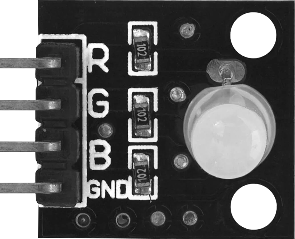
The AZDelivery KY-016 RGB LED module is a versatile light-emitting diode (LED) component capable of producing a wide range of colors by mixing red, green, and blue light. This module is ideal for applications requiring dynamic lighting effects, such as displays, decorative lighting, and status indicators. Its compact design and ease of use make it a popular choice for hobbyists, students, and professionals working on Arduino or other microcontroller-based projects.
Explore Projects Built with Led module RGB
 Open Project in Cirkit Designer
 Open Project in Cirkit Designer
 Open Project in Cirkit Designer
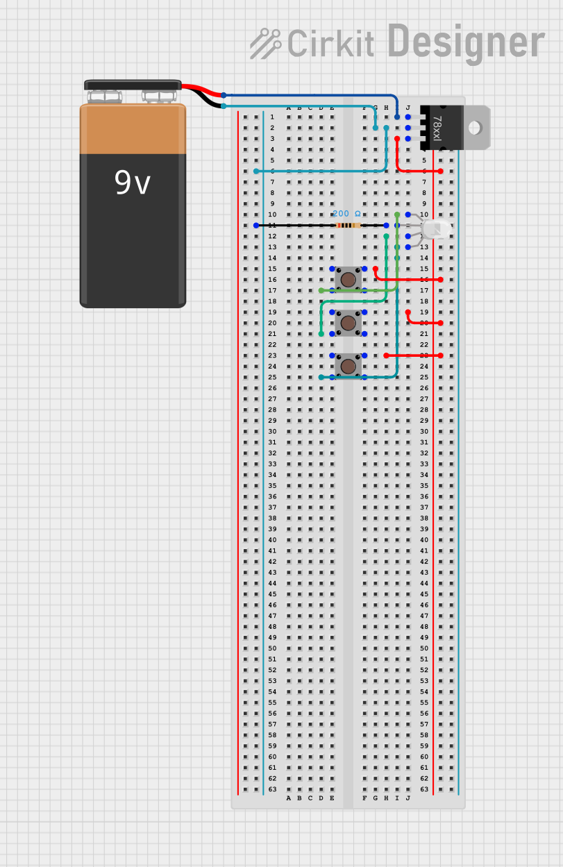 Open Project in Cirkit Designer
Explore Projects Built with Led module RGB
Open Project in Cirkit DesignerOpen Project in Cirkit DesignerOpen Project in Cirkit DesignerOpen Project in Cirkit DesignerTechnical Specifications
The following table outlines the key technical details of the KY-016 RGB LED module:
| Parameter | Value |
|---|---|
| Manufacturer | AZDelivery |
| Part ID | KY-016 |
| Operating Voltage | 3.3V - 5V |
| Operating Current | 20mA per channel (typical) |
| LED Colors | Red, Green, Blue (RGB) |
| Control Method | PWM (Pulse Width Modulation) |
| Dimensions | 18mm x 15mm x 3mm |
| Connector Type | 4-pin header |
Pin Configuration and Descriptions
The KY-016 module has a 4-pin header for easy interfacing. The pin configuration is as follows:
| Pin | Name | Description |
|---|---|---|
| 1 | R | Red LED control pin (connect to PWM pin on MCU) |
| 2 | G | Green LED control pin (connect to PWM pin on MCU) |
| 3 | B | Blue LED control pin (connect to PWM pin on MCU) |
| 4 | GND | Ground connection |
Usage Instructions
How to Use the KY-016 RGB LED Module in a Circuit
- Power Supply: Connect the GND pin of the module to the ground of your power source or microcontroller. The R, G, and B pins should be connected to PWM-capable pins on your microcontroller.
- PWM Control: Use Pulse Width Modulation (PWM) signals to control the brightness of each color channel (Red, Green, and Blue). By varying the duty cycle of the PWM signals, you can mix colors to achieve the desired output.
- Resistors: If the module does not include built-in resistors, add appropriate current-limiting resistors (typically 220Ω to 330Ω) in series with the R, G, and B pins to prevent damage to the LEDs.
Example Arduino UNO Code
The following example demonstrates how to control the KY-016 RGB LED module using an Arduino UNO:
// Define the PWM pins connected to the RGB module
const int redPin = 9;   // Connect to R pin of KY-016
const int greenPin = 10; // Connect to G pin of KY-016
const int bluePin = 11;  // Connect to B pin of KY-016

void setup() {
  // Set the RGB pins as output
  pinMode(redPin, OUTPUT);
  pinMode(greenPin, OUTPUT);
  pinMode(bluePin, OUTPUT);
}

void loop() {
  // Example: Cycle through Red, Green, and Blue colors
  setColor(255, 0, 0); // Red
  delay(1000);         // Wait 1 second
  setColor(0, 255, 0); // Green
  delay(1000);         // Wait 1 second
  setColor(0, 0, 255); // Blue
  delay(1000);         // Wait 1 second
}

// Function to set RGB color
void setColor(int redValue, int greenValue, int blueValue) {
  analogWrite(redPin, redValue);   // Set Red brightness
  analogWrite(greenPin, greenValue); // Set Green brightness
  analogWrite(bluePin, blueValue);  // Set Blue brightness
}
Important Considerations and Best Practices
- Voltage Compatibility: Ensure the module is powered within its operating voltage range (3.3V - 5V).
- Current Limiting: Use appropriate resistors if the module does not include built-in current-limiting resistors.
- PWM Pins: For smooth color transitions, connect the R, G, and B pins to PWM-capable pins on your microcontroller.
- Heat Management: Avoid running the LEDs at maximum brightness for extended periods to prevent overheating.
Troubleshooting and FAQs
Common Issues and Solutions
LEDs Not Lighting Up:
- Verify all connections, especially the GND pin.
- Check if the microcontroller is supplying the correct PWM signals.
- Ensure the power supply voltage is within the specified range.
Incorrect Colors Displayed:
- Confirm that the R, G, and B pins are connected to the correct microcontroller pins.
- Check the PWM values being sent to each channel.
Flickering or Unstable Output:
- Ensure a stable power supply to the module.
- Verify that the PWM frequency is appropriate for the LEDs.
Overheating:
- Reduce the duty cycle of the PWM signals to lower the brightness.
- Add current-limiting resistors if not already included.
FAQs
Q: Can I use the KY-016 module with a 3.3V microcontroller?
A: Yes, the module is compatible with both 3.3V and 5V systems. Ensure the PWM signals match the operating voltage.
Q: How do I achieve white light with the KY-016 module?
A: To produce white light, set the PWM values of the R, G, and B channels to equal intensities (e.g., setColor(255, 255, 255)).
Q: Can I control the KY-016 module without PWM?
A: While possible, using PWM is recommended for precise brightness and color control. Without PWM, you can only turn the LEDs fully on or off.
Q: Does the module include built-in resistors?
A: Some versions of the KY-016 module include built-in resistors, while others do not. Check the product documentation or measure the resistance to confirm.