How to Use poweroptimizer: Examples, Pinouts, and Specs

 Design with poweroptimizer in Cirkit Designer
Introduction
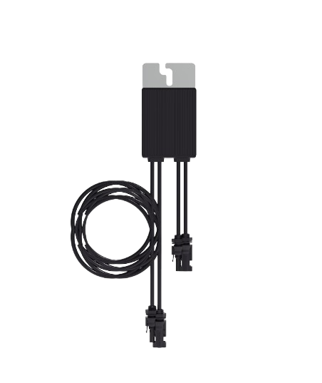
A power optimizer is an advanced electronic component designed to enhance the efficiency of solar panels. It operates by individually tracking the Maximum Power Point (MPP) of each solar module, ensuring that each panel operates at its peak performance regardless of the performance of other panels in the array. This is particularly useful in scenarios where panels are partially shaded or have different orientations. Power optimizers are commonly used in photovoltaic (PV) systems to maximize energy production and provide module-level monitoring and control.
Explore Projects Built with poweroptimizer

 Open Project in Cirkit Designer
 Open Project in Cirkit Designer
 Open Project in Cirkit Designer
 Open Project in Cirkit Designer
Explore Projects Built with poweroptimizer

 Open Project in Cirkit Designer
 Open Project in Cirkit Designer
 Open Project in Cirkit Designer
 Open Project in Cirkit Designer
Common Applications and Use Cases
- Residential and commercial solar installations
- PV systems with panels experiencing partial shading
- Installations with panels facing multiple orientations
- Systems requiring module-level performance monitoring
Technical Specifications
Key Technical Details
| Specification | Detail |
|---|---|
| Operating Voltage | XX V - XX V |
| Maximum Input Current | XX A |
| Maximum Efficiency | XX% |
| Operating Temperature Range | -XX°C to +XX°C |
| Communication Interface | RS485, ZigBee, etc. |
| Compatibility | Compatible with XX W - XX W solar panels |
Pin Configuration and Descriptions
| Pin Number | Name | Description |
|---|---|---|
| 1 | V+ | Positive voltage input from the solar panel |
| 2 | V- | Negative voltage input from the solar panel |
| 3 | Vout+ | Optimized positive voltage output |
| 4 | Vout- | Optimized negative voltage output |
| 5 | COM | Communication pin for monitoring |
Usage Instructions
How to Use the Component in a Circuit
- Connection to Solar Panels: Connect the positive and negative terminals of the solar panel to the V+ and V- pins of the power optimizer, respectively.
- Output Connection: Connect the Vout+ and Vout- to the input terminals of the inverter or the next power optimizer in series.
- Communication Setup: Connect the COM pin to the data logger or monitoring system using the appropriate communication protocol.
- Configuration: Configure the power optimizer settings according to the specifications of the connected solar panel and the requirements of the PV system.
Important Considerations and Best Practices
- Ensure that the voltage and current ratings of the solar panels do not exceed the specifications of the power optimizer.
- Install the power optimizer in a location that minimizes exposure to moisture and extreme temperatures.
- Use appropriate cable sizes and protection devices such as fuses or circuit breakers as per the electrical codes.
- Regularly monitor the performance of each power optimizer to detect any potential issues early.
Troubleshooting and FAQs
Common Issues
- Reduced Power Output: Check for shading or debris on the solar panels. Ensure that all connections are secure and free of corrosion.
- Communication Errors: Verify the integrity of the communication wiring and the settings of the monitoring system.
- Overheating: Ensure adequate ventilation around the power optimizer and check for any environmental factors contributing to high temperatures.
Solutions and Tips for Troubleshooting
- Regular Maintenance: Keep the solar panels clean and inspect the power optimizer for any signs of damage or wear.
- Firmware Updates: Keep the power optimizer firmware up to date to ensure optimal performance and compatibility.
- Professional Assistance: If issues persist, contact a certified technician for further diagnosis and repair.
FAQs
Q: Can power optimizers be used with any type of solar panel? A: Power optimizers are compatible with a wide range of solar panels, but it is important to match the optimizer's specifications with the panel's electrical characteristics.
Q: How do power optimizers improve energy production? A: By tracking the MPP of each panel, power optimizers ensure that each panel operates at its maximum potential, increasing the overall energy yield of the system.
Q: Is it necessary to use a power optimizer for every solar panel? A: While it is not strictly necessary, using a power optimizer for each panel allows for individual panel optimization and monitoring, which can be beneficial in maximizing system performance.
Q: What is the impact of partial shading on a solar panel without a power optimizer? A: Partial shading can significantly reduce the power output of a solar panel. Without a power optimizer, the performance of the entire string of panels can be affected by a single shaded panel.
Q: Can power optimizers communicate with smart home systems? A: Many power optimizers offer communication features that can integrate with smart home systems for advanced monitoring and control. Check the manufacturer's specifications for compatibility details.
Example Code for Arduino UNO Integration
// Example code for integrating a power optimizer with an Arduino UNO for monitoring purposes.
// This code assumes the use of a serial communication protocol.

#include <SoftwareSerial.h>

SoftwareSerial powerOptimizerSerial(10, 11); // RX, TX

void setup() {
  // Begin serial communication with the power optimizer at 9600 baud rate.
  powerOptimizerSerial.begin(9600);
  Serial.begin(9600); // Begin serial communication with the computer for debugging.
}

void loop() {
  // Check if data is available from the power optimizer.
  if (powerOptimizerSerial.available()) {
    // Read the data and print it to the serial monitor.
    String optimizerData = powerOptimizerSerial.readStringUntil('\n');
    Serial.println(optimizerData);
  }
  // Add a delay between reads for stability.
  delay(1000);
}
Note: The example code provided is for illustrative purposes and may require modification to work with specific power optimizer models and communication protocols. Always refer to the manufacturer's datasheet for accurate programming and integration instructions.