How to Use ESP32 38PIN: Examples, Pinouts, and Specs
Introduction
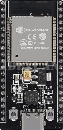
The ESP32 38PIN is a powerful and versatile microcontroller designed for Internet of Things (IoT) applications. It integrates both Wi-Fi and Bluetooth capabilities, making it ideal for wireless communication and smart device projects. With its 38 pins, the ESP32 offers a wide range of GPIOs, ADCs, and communication interfaces, enabling developers to create complex and feature-rich systems. Its compact size and robust performance make it a popular choice for hobbyists and professionals alike.
Explore Projects Built with ESP32 38PIN


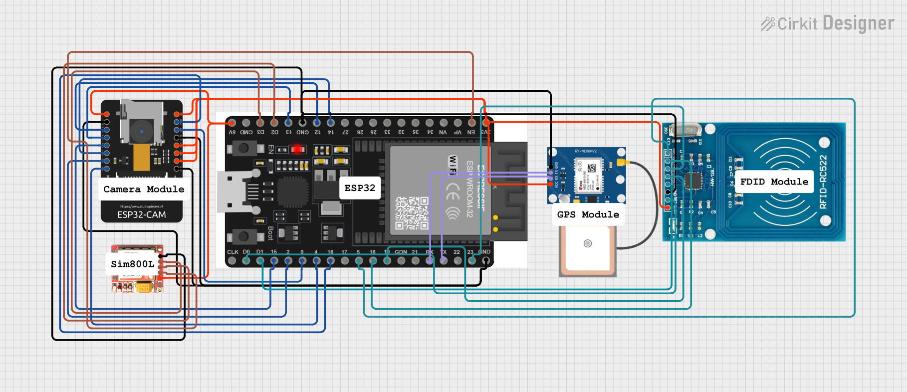
Explore Projects Built with ESP32 38PIN
Common Applications and Use Cases
- Home automation systems
- Wireless sensor networks
- Smart appliances
- Wearable devices
- Industrial IoT solutions
- Robotics and automation
- Real-time data monitoring and logging
Technical Specifications
The ESP32 38PIN microcontroller is packed with features that make it suitable for a variety of applications. Below are its key technical details:
Key Technical Details
- Processor: Dual-core Xtensa® 32-bit LX6 CPU
- Clock Speed: Up to 240 MHz
- Flash Memory: 4 MB (varies by model)
- SRAM: 520 KB
- Wi-Fi: 802.11 b/g/n
- Bluetooth: v4.2 BR/EDR and BLE
- Operating Voltage: 3.3V
- GPIO Pins: 30+ (configurable for digital I/O, PWM, etc.)
- ADC Channels: Up to 18 (12-bit resolution)
- DAC Channels: 2
- Communication Interfaces: UART, SPI, I2C, I2S, CAN
- Power Consumption: Ultra-low power modes available
- Operating Temperature: -40°C to +125°C
Pin Configuration and Descriptions
The ESP32 38PIN has 38 pins, each with specific functions. Below is a table summarizing the key pins and their descriptions:
| Pin Number | Pin Name | Function |
|---|---|---|
| 1 | EN | Enable pin. Pulling this pin high enables the chip. |
| 2 | IO0 | GPIO0. Can be used for input/output or boot mode selection. |
| 3 | IO1 (TX0) | GPIO1. UART0 TX pin. |
| 4 | IO3 (RX0) | GPIO3. UART0 RX pin. |
| 5 | IO4 | GPIO4. General-purpose input/output. |
| 6 | IO5 | GPIO5. General-purpose input/output. |
| 7 | IO12 | GPIO12. Can be used as an ADC or touch sensor input. |
| 8 | IO13 | GPIO13. Can be used as an ADC or touch sensor input. |
| 9 | IO14 | GPIO14. Supports PWM, ADC, and other functions. |
| 10 | IO15 | GPIO15. Supports PWM, ADC, and other functions. |
| 11 | IO16 | GPIO16. General-purpose input/output. |
| 12 | IO17 | GPIO17. General-purpose input/output. |
| 13 | IO18 | GPIO18. SPI clock (SCK) or general-purpose input/output. |
| 14 | IO19 | GPIO19. SPI data (MISO) or general-purpose input/output. |
| 15 | IO21 | GPIO21. I2C data (SDA) or general-purpose input/output. |
| 16 | IO22 | GPIO22. I2C clock (SCL) or general-purpose input/output. |
| 17 | IO23 | GPIO23. SPI data (MOSI) or general-purpose input/output. |
| 18 | GND | Ground. Connect to the ground of the power supply. |
| 19 | 3V3 | 3.3V power supply input. |
| 20 | VIN | Input voltage (5V). |
Note: Not all pins are listed here. Refer to the ESP32 datasheet for a complete pinout.
Usage Instructions
The ESP32 38PIN is easy to use in a variety of circuits. Below are the steps and best practices for using this microcontroller:
How to Use the ESP32 38PIN in a Circuit
Powering the ESP32:
- Connect the VIN pin to a 5V power source or the 3V3 pin to a 3.3V power source.
- Ensure the ground (GND) is connected to the power supply ground.
Programming the ESP32:
- Use a USB-to-serial adapter or a development board with a built-in USB interface.
- Install the ESP32 board package in the Arduino IDE or use the ESP-IDF framework for advanced development.
Connecting Peripherals:
- Use GPIO pins for digital input/output.
- Connect sensors to ADC pins for analog input.
- Use UART, SPI, or I2C for communication with other devices.
Uploading Code:
- Select the correct board and port in the Arduino IDE.
- Write or load your code and click the upload button.
Example Code for Arduino IDE
Below is an example of how to blink an LED connected to GPIO2:
// Define the GPIO pin for the LED
#define LED_PIN 2

void setup() {
  pinMode(LED_PIN, OUTPUT); // Set GPIO2 as an output pin
}

void loop() {
  digitalWrite(LED_PIN, HIGH); // Turn the LED on
  delay(1000);                 // Wait for 1 second
  digitalWrite(LED_PIN, LOW);  // Turn the LED off
  delay(1000);                 // Wait for 1 second
}
Important Considerations and Best Practices
- Voltage Levels: Ensure all connected peripherals operate at 3.3V logic levels to avoid damaging the ESP32.
- Boot Mode: GPIO0 must be pulled low during boot to enter programming mode.
- Power Supply: Use a stable power supply to avoid unexpected resets or malfunctions.
- Heat Management: If running at high performance, consider adding a heatsink to manage heat dissipation.
Troubleshooting and FAQs
Common Issues and Solutions
ESP32 Not Detected by the Computer:
- Ensure the correct USB driver is installed for your USB-to-serial adapter.
- Check the USB cable for damage or try a different cable.
Code Upload Fails:
- Verify that GPIO0 is pulled low during programming.
- Check the selected board and port in the Arduino IDE.
Wi-Fi Connection Issues:
- Ensure the correct SSID and password are used in your code.
- Check for interference or weak signal strength.
Random Resets or Instability:
- Use a stable power supply with sufficient current (at least 500mA).
- Check for loose connections or short circuits.
FAQs
Q: Can I power the ESP32 with a 5V power source?
A: Yes, you can power the ESP32 through the VIN pin with a 5V source.
Q: How do I use the ESP32's Bluetooth functionality?
A: Use the BluetoothSerial library in the Arduino IDE or the ESP-IDF framework to implement Bluetooth communication.
Q: Can I use the ESP32 with 5V logic devices?
A: No, the ESP32 operates at 3.3V logic levels. Use a level shifter to interface with 5V devices.
Q: What is the maximum current draw of the ESP32?
A: The ESP32 can draw up to 500mA during peak operation, so ensure your power supply can handle this.
This concludes the documentation for the ESP32 38PIN. For more details, refer to the official ESP32 datasheet and programming guides.