
How to Use PSP_TOUCH_CONNECTOR: Examples, Pinouts, and Specs
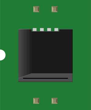
 Design with PSP_TOUCH_CONNECTOR in Cirkit Designer
Introduction
The PSP_TOUCH_CONNECTOR (Manufacturer Part ID: LCD-08448) by SparkFun is a specialized connector designed to interface with touch screens in PlayStation Portable (PSP) devices. It facilitates the transmission of touch input signals from the screen to the processing unit, enabling seamless interaction with the device. This component is compact, reliable, and ideal for projects involving PSP touch screen integration or similar applications.
Explore Projects Built with PSP_TOUCH_CONNECTOR
 Open Project in Cirkit Designer
 Open Project in Cirkit Designer
 Open Project in Cirkit Designer
 Open Project in Cirkit Designer
Explore Projects Built with PSP_TOUCH_CONNECTOR
Open Project in Cirkit DesignerOpen Project in Cirkit DesignerOpen Project in Cirkit DesignerOpen Project in Cirkit DesignerCommon Applications and Use Cases
- Interfacing PSP touch screens with custom electronics or microcontrollers.
- Repairing or replacing damaged PSP touch screen connectors.
- Prototyping touch-enabled devices using PSP touch screens.
- Educational projects involving touch screen technology.
Technical Specifications
The PSP_TOUCH_CONNECTOR is a compact and robust component with the following specifications:
| Parameter | Value |
|---|---|
| Manufacturer | SparkFun |
| Part ID | LCD-08448 |
| Connector Type | Flat Flexible Cable (FFC) |
| Number of Pins | 12 |
| Pin Pitch | 0.5 mm |
| Operating Voltage | 3.3V to 5V |
| Maximum Current | 500 mA |
| Dimensions | 15 mm x 5 mm x 2 mm |
| Operating Temperature | -20°C to 70°C |
Pin Configuration and Descriptions
The PSP_TOUCH_CONNECTOR has a 12-pin configuration. Below is the pinout and description:
| Pin Number | Name | Description |
|---|---|---|
| 1 | VCC | Power supply input (3.3V to 5V). |
| 2 | GND | Ground connection. |
| 3 | X+ | Positive X-axis signal from the touch screen. |
| 4 | X- | Negative X-axis signal from the touch screen. |
| 5 | Y+ | Positive Y-axis signal from the touch screen. |
| 6 | Y- | Negative Y-axis signal from the touch screen. |
| 7 | INT | Interrupt signal for touch detection. |
| 8 | SCL | Serial Clock Line for I2C communication. |
| 9 | SDA | Serial Data Line for I2C communication. |
| 10 | RESET | Reset signal for the touch controller. |
| 11 | NC | Not connected (reserved for future use). |
| 12 | NC | Not connected (reserved for future use). |
Usage Instructions
How to Use the PSP_TOUCH_CONNECTOR in a Circuit
Connecting the Touch Screen:
- Align the flat flexible cable (FFC) of the PSP touch screen with the connector.
- Insert the cable into the connector slot and secure it using the locking mechanism.
Wiring to a Microcontroller:
- Connect the VCC and GND pins to the power supply of your circuit.
- Use the X+, X-, Y+, and Y- pins to read analog touch signals if using an analog interface.
- For I2C communication, connect the SCL and SDA pins to the corresponding pins on your microcontroller.
- Use the INT pin to detect touch events and the RESET pin to initialize the touch controller.
Programming:
- If using an Arduino UNO, you can use the I2C interface to communicate with the touch screen. Below is an example code snippet:
#include <Wire.h> // Include the Wire library for I2C communication

#define TOUCH_SCL A5 // Define the SCL pin (Arduino UNO default is A5)
#define TOUCH_SDA A4 // Define the SDA pin (Arduino UNO default is A4)
#define TOUCH_INT 2  // Define the interrupt pin for touch detection

void setup() {
  Wire.begin(); // Initialize I2C communication
  pinMode(TOUCH_INT, INPUT); // Set the interrupt pin as input
  Serial.begin(9600); // Start serial communication for debugging

  // Optional: Reset the touch controller
  pinMode(RESET, OUTPUT);
  digitalWrite(RESET, LOW);
  delay(10);
  digitalWrite(RESET, HIGH);
  delay(100);
}

void loop() {
  if (digitalRead(TOUCH_INT) == LOW) {
    // If a touch is detected, read data from the touch screen
    Wire.beginTransmission(0x38); // Replace 0x38 with the I2C address of your touch controller
    Wire.write(0x00); // Command to read touch data (check your touch controller datasheet)
    Wire.endTransmission();
    Wire.requestFrom(0x38, 4); // Request 4 bytes of touch data

    if (Wire.available() == 4) {
      int x = Wire.read(); // Read X-coordinate
      int y = Wire.read(); // Read Y-coordinate
      int z = Wire.read(); // Read touch pressure (if supported)
      int touchID = Wire.read(); // Read touch ID (if supported)

      Serial.print("X: ");
      Serial.print(x);
      Serial.print(", Y: ");
      Serial.print(y);
      Serial.print(", Pressure: ");
      Serial.println(z);
    }
  }
}
Important Considerations and Best Practices
- Ensure the FFC is inserted correctly into the connector to avoid damage.
- Use appropriate pull-up resistors on the I2C lines (SCL and SDA) if not already present.
- Avoid exceeding the voltage and current ratings to prevent damage to the connector or touch screen.
- Handle the connector and FFC with care to avoid bending or breaking the delicate pins.
Troubleshooting and FAQs
Common Issues and Solutions
Touch Screen Not Responding:
- Verify that the FFC is securely connected to the PSP_TOUCH_CONNECTOR.
- Check the power supply voltage and ensure it is within the specified range (3.3V to 5V).
- Confirm that the I2C lines (SCL and SDA) are correctly wired and have proper pull-up resistors.
Incorrect Touch Data:
- Ensure the X+, X-, Y+, and Y- pins are correctly connected if using an analog interface.
- Check for noise or interference on the signal lines and use proper shielding if necessary.
Connector Damage:
- Inspect the connector for bent or broken pins. Replace the connector if damaged.
FAQs
Q: Can the PSP_TOUCH_CONNECTOR be used with other touch screens?
A: Yes, as long as the touch screen uses a compatible 12-pin FFC and operates within the specified voltage and current ratings.
Q: What is the I2C address of the touch controller?
A: The I2C address depends on the specific touch controller used. Refer to the datasheet of your touch screen's controller for the correct address.
Q: Do I need external pull-up resistors for I2C communication?
A: Yes, if your circuit or microcontroller does not already include pull-up resistors on the SCL and SDA lines.
Q: Can this connector handle multi-touch signals?
A: Multi-touch capability depends on the touch screen and its controller, not the connector itself.
This concludes the documentation for the PSP_TOUCH_CONNECTOR. For further assistance, refer to SparkFun's official resources or contact their support team.