Cirkit Designer Logo
Cirkit Designer
Your all-in-one circuit design IDE
Home / 
Component Documentation

How to Use 433MHz RF Receiver: Examples, Pinouts, and Specs

Image of 433MHz RF Receiver
Cirkit Designer LogoDesign with 433MHz RF Receiver in Cirkit Designer

Introduction

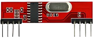
The 433MHz RF Receiver is a device designed to receive radio frequency signals at a frequency of 433 MHz. It is widely used in wireless communication systems due to its simplicity, low cost, and efficiency. This component is commonly paired with a 433MHz RF Transmitter to enable wireless data transmission over short to medium distances. Typical applications include remote controls, wireless sensors, home automation systems, and Internet of Things (IoT) devices.

Explore Projects Built with 433MHz RF Receiver

Use Cirkit Designer to design, explore, and prototype these projects online. Some projects support real-time simulation. Click "Open Project" to start designing instantly!
433 MHz RF Transmitter and Receiver with Arduino UNO for Wireless Communication
Image of Wireless Communication: A project utilizing 433MHz RF Receiver in a practical application
This circuit consists of two Arduino UNO microcontrollers, each connected to an RF 433 MHz Transmitter and a 433 MHz RF Receiver Module. The setup allows for wireless communication between the two Arduinos, enabling them to send and receive data over a 433 MHz RF link.
Cirkit Designer LogoOpen Project in Cirkit Designer
ESP32-Based RF Communication System with 433 MHz Modules
Image of 433 mhz: A project utilizing 433MHz RF Receiver in a practical application
This circuit comprises an ESP32 microcontroller connected to a 433 MHz RF transmitter and receiver pair. The ESP32 is programmed to receive and decode RF signals through the receiver module, as well as send RF signals via the transmitter module. Additionally, the ESP32 can communicate with a Bluetooth device to exchange commands and data, and it uses an LED for status indication.
Cirkit Designer LogoOpen Project in Cirkit Designer
433 MHz RF Transmitter and Receiver with Arduino Uno for Wireless LED Control
Image of rf module up: A project utilizing 433MHz RF Receiver in a practical application
This circuit consists of two Arduino Uno R3 microcontrollers communicating wirelessly using 433 MHz RF modules. One Arduino is connected to an RF transmitter to send data, while the other Arduino is connected to an RF receiver to receive data and control an LED based on the received signal.
Cirkit Designer LogoOpen Project in Cirkit Designer
Arduino UNO with 433MHz RF Module for Wireless Communication
Image of Receiver: A project utilizing 433MHz RF Receiver in a practical application
This circuit consists of an Arduino UNO connected to an RXN433MHz radio frequency module. The Arduino provides 5V power and ground to the RF module and is configured to communicate with it via digital pin D11. Additionally, a multimeter is connected with alligator clip cables to measure the voltage supplied to the RF module.
Cirkit Designer LogoOpen Project in Cirkit Designer

Explore Projects Built with 433MHz RF Receiver

Use Cirkit Designer to design, explore, and prototype these projects online. Some projects support real-time simulation. Click "Open Project" to start designing instantly!
Image of Wireless Communication: A project utilizing 433MHz RF Receiver in a practical application
433 MHz RF Transmitter and Receiver with Arduino UNO for Wireless Communication
This circuit consists of two Arduino UNO microcontrollers, each connected to an RF 433 MHz Transmitter and a 433 MHz RF Receiver Module. The setup allows for wireless communication between the two Arduinos, enabling them to send and receive data over a 433 MHz RF link.
Cirkit Designer LogoOpen Project in Cirkit Designer
Image of 433 mhz: A project utilizing 433MHz RF Receiver in a practical application
ESP32-Based RF Communication System with 433 MHz Modules
This circuit comprises an ESP32 microcontroller connected to a 433 MHz RF transmitter and receiver pair. The ESP32 is programmed to receive and decode RF signals through the receiver module, as well as send RF signals via the transmitter module. Additionally, the ESP32 can communicate with a Bluetooth device to exchange commands and data, and it uses an LED for status indication.
Cirkit Designer LogoOpen Project in Cirkit Designer
Image of rf module up: A project utilizing 433MHz RF Receiver in a practical application
433 MHz RF Transmitter and Receiver with Arduino Uno for Wireless LED Control
This circuit consists of two Arduino Uno R3 microcontrollers communicating wirelessly using 433 MHz RF modules. One Arduino is connected to an RF transmitter to send data, while the other Arduino is connected to an RF receiver to receive data and control an LED based on the received signal.
Cirkit Designer LogoOpen Project in Cirkit Designer
Image of Receiver: A project utilizing 433MHz RF Receiver in a practical application
Arduino UNO with 433MHz RF Module for Wireless Communication
This circuit consists of an Arduino UNO connected to an RXN433MHz radio frequency module. The Arduino provides 5V power and ground to the RF module and is configured to communicate with it via digital pin D11. Additionally, a multimeter is connected with alligator clip cables to measure the voltage supplied to the RF module.
Cirkit Designer LogoOpen Project in Cirkit Designer

Technical Specifications

  • Frequency Range: 433.92 MHz (±150 kHz)
  • Operating Voltage: 3.3V to 5V DC
  • Operating Current: ≤5.5 mA
  • Sensitivity: -105 dBm (typical)
  • Data Rate: 2 kbps (maximum)
  • Modulation Type: Amplitude Shift Keying (ASK)
  • Operating Temperature: -20°C to +70°C
  • Range: Up to 50 meters (line of sight, depending on environment)

Pin Configuration and Descriptions

The 433MHz RF Receiver typically has 4 pins. The table below describes each pin:

Pin Name Description
1 VCC Power supply pin. Connect to 3.3V or 5V DC.
2 DATA Data output pin. Outputs the received digital signal.
3 DATA Duplicate data output pin (can be used interchangeably with Pin 2).
4 GND Ground pin. Connect to the ground of the power supply.

Usage Instructions

How to Use the 433MHz RF Receiver in a Circuit

  1. Power the Receiver: Connect the VCC pin to a 3.3V or 5V DC power source and the GND pin to the ground.
  2. Connect the Data Pin: Use either of the DATA pins to connect the receiver to a microcontroller or other processing unit.
  3. Antenna Connection: For optimal performance, attach a 17 cm wire to the antenna input (if available) to improve signal reception.
  4. Pair with a Transmitter: Ensure the 433MHz RF Transmitter is configured to send data at the same frequency and modulation type.

Important Considerations and Best Practices

  • Antenna Placement: Use a properly sized antenna (17 cm for 433 MHz) and position it away from interference sources like metal objects or other RF devices.
  • Power Supply: Ensure a stable power supply to avoid noise or signal distortion.
  • Environment: The range of the receiver can be affected by obstacles, walls, and interference. For best results, maintain a clear line of sight between the transmitter and receiver.
  • Data Decoding: The raw data received from the DATA pin may need to be decoded using a microcontroller or software library.

Example: Using the 433MHz RF Receiver with Arduino UNO

Below is an example of how to use the 433MHz RF Receiver with an Arduino UNO to receive data:

#include <RCSwitch.h> // Include the RC-Switch library for decoding RF signals

RCSwitch mySwitch = RCSwitch();

void setup() {
  Serial.begin(9600); // Initialize serial communication at 9600 baud
  mySwitch.enableReceive(0); // Enable receiver on interrupt pin 2 (Arduino UNO pin 2)
}

void loop() {
  if (mySwitch.available()) {
    // Check if a signal is received
    int receivedValue = mySwitch.getReceivedValue();
    
    if (receivedValue == 0) {
      Serial.println("Unknown signal received"); // Print error if signal is invalid
    } else {
      Serial.print("Received signal: ");
      Serial.println(receivedValue); // Print the received signal value
    }
    
    mySwitch.resetAvailable(); // Reset the receiver to listen for the next signal
  }
}

Note: The RC-Switch library must be installed in the Arduino IDE. You can install it via the Library Manager.

Troubleshooting and FAQs

Common Issues

  1. No Signal Received:

    • Ensure the transmitter and receiver are operating at the same frequency (433 MHz).
    • Check the antenna connection and placement.
    • Verify that the transmitter is powered and sending data.
  2. Interference or Noise:

    • Use a decoupling capacitor (e.g., 0.1 µF) between VCC and GND to reduce power supply noise.
    • Avoid placing the receiver near other RF devices or sources of electromagnetic interference.
  3. Short Range:

    • Ensure a clear line of sight between the transmitter and receiver.
    • Use a properly sized antenna (17 cm for 433 MHz).

FAQs

Q: Can I use the 433MHz RF Receiver with a 3.3V microcontroller?
A: Yes, the receiver operates at both 3.3V and 5V. Ensure the data pin voltage is compatible with your microcontroller.

Q: What is the maximum range of the 433MHz RF Receiver?
A: The range is up to 50 meters in an open environment with a clear line of sight. Obstacles and interference can reduce the range.

Q: How do I decode the received data?
A: Use a microcontroller with a library like RC-Switch to decode the received signals. The library simplifies the process of interpreting the raw data.

Q: Can I use multiple receivers in the same area?
A: Yes, but ensure that each transmitter is uniquely coded to avoid interference between signals.