How to Use I/O Expansion Shield For Arduino Nano: Examples, Pinouts, and Specs
Introduction
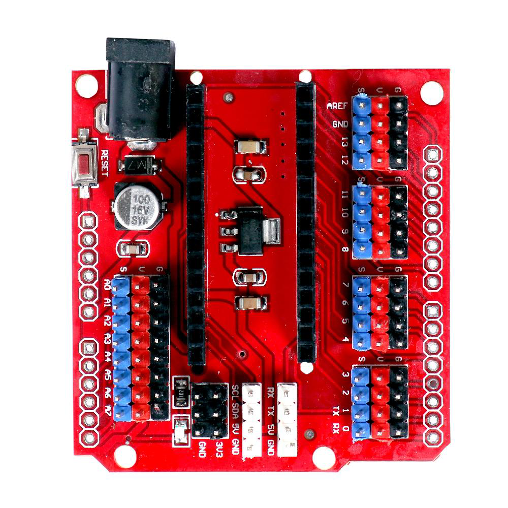
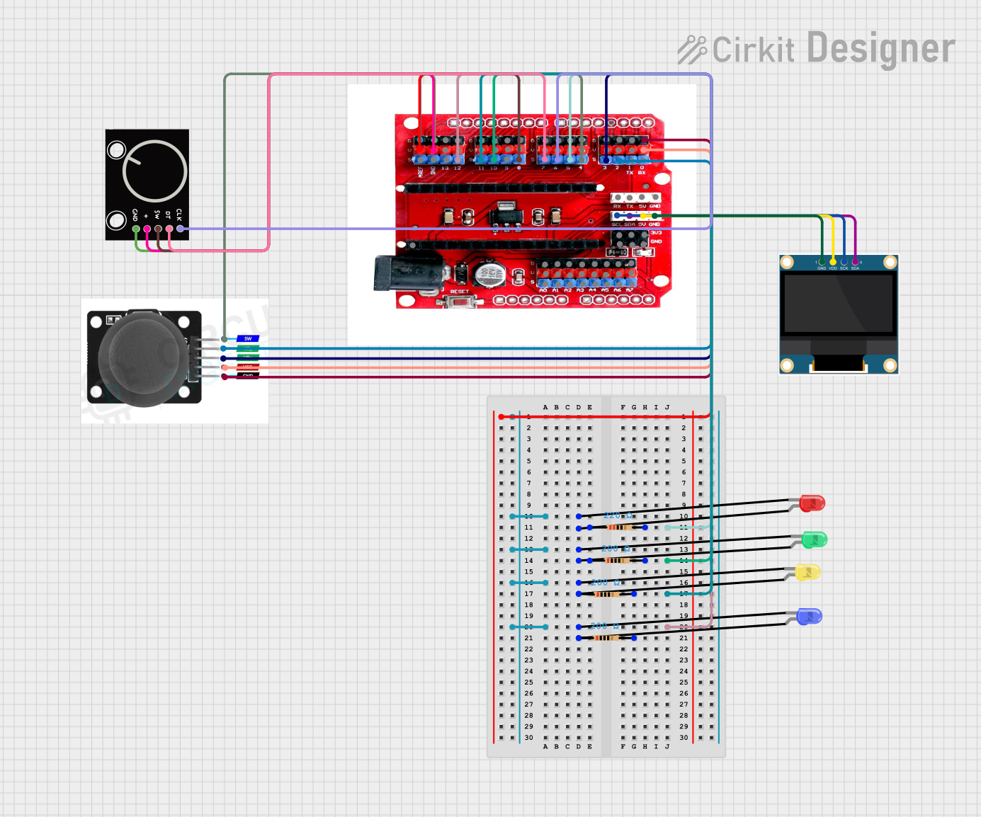
The I/O Expansion Shield for Arduino Nano is a versatile and compact add-on board designed to enhance the capabilities of an Arduino Nano by providing additional input/output (I/O) pins and functionalities. This shield is ideal for hobbyists, educators, and prototyping professionals who require more I/O options for their projects. Common applications include robotics, home automation, sensor networks, and DIY electronics.
Explore Projects Built with I/O Expansion Shield For Arduino Nano
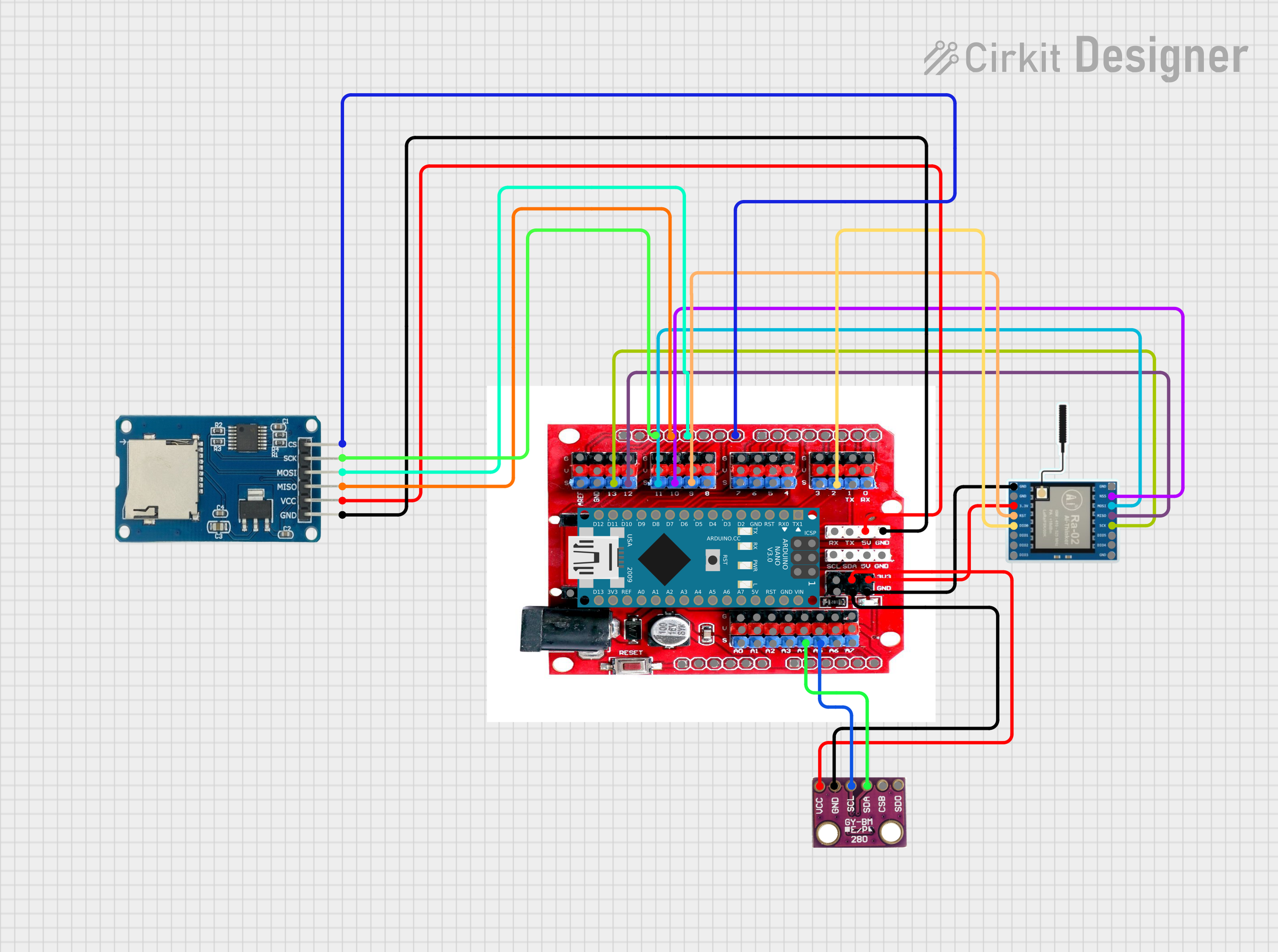
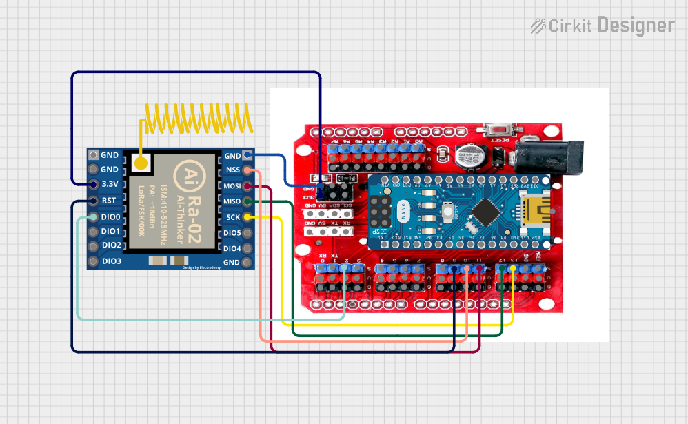
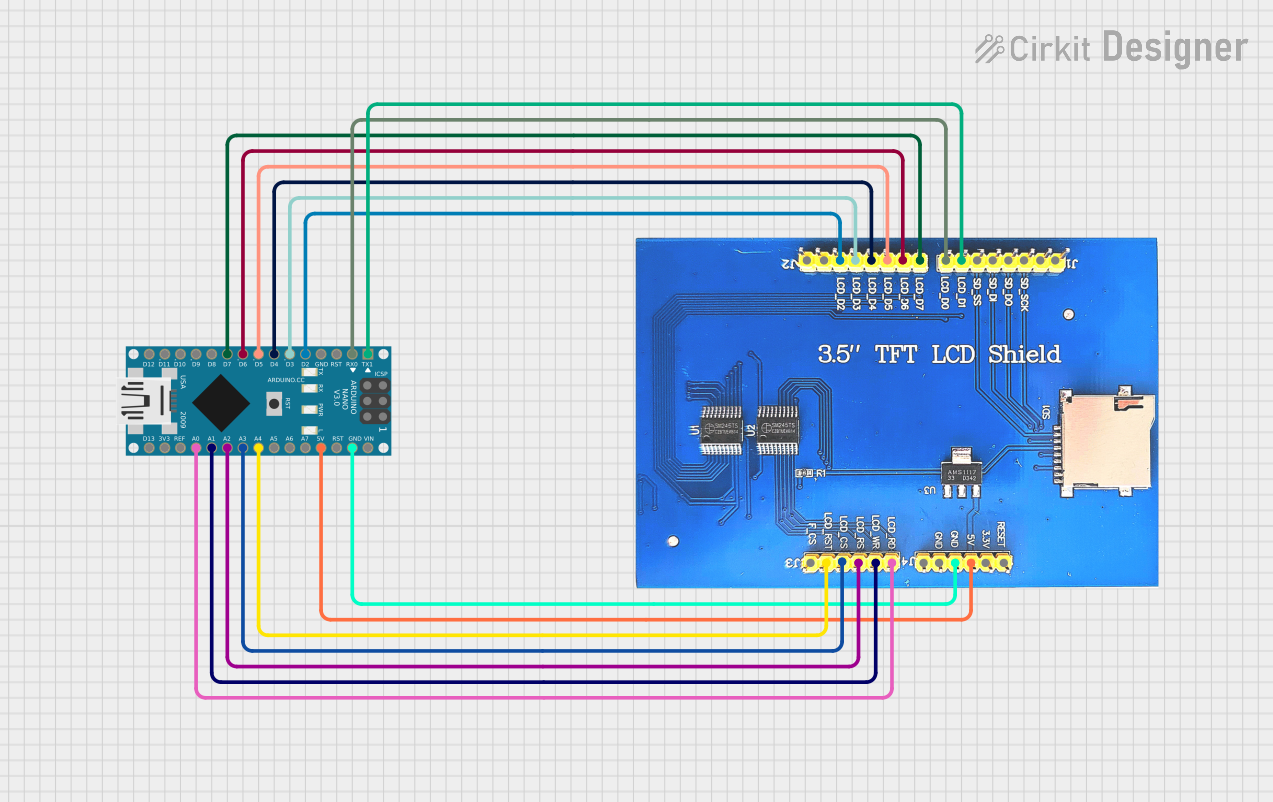
Explore Projects Built with I/O Expansion Shield For Arduino Nano
Technical Specifications
Key Technical Details
- Operating Voltage: 5V (supplied by the Arduino Nano)
- I/O Expansion: Additional digital and analog pins
- Communication Interfaces: I2C, SPI, UART
- Form Factor: Compatible with Arduino Nano
Pin Configuration and Descriptions
| Pin Number | Function | Description |
|---|---|---|
| D0-D13 | Digital I/O | Digital pins, identical to the Arduino Nano |
| A0-A7 | Analog Inputs | Analog input pins, extended beyond the Nano's A0-A5 |
| A4, A5 | I2C Interface | SDA (A4) and SCL (A5) for I2C communication |
| D10-D13 | SPI Interface | SPI communication using standard pins |
| D0, D1 | UART Interface | RX (D0) and TX (D1) for serial communication |
| RST | Reset | Connected to the Arduino Nano's reset pin |
| 3V3, 5V | Power Supply | Voltage outputs from the Arduino Nano |
| GND | Ground | Ground pins |
Usage Instructions
How to Use the Component in a Circuit
- Mounting the Shield: Carefully align the expansion shield pins with the headers on the Arduino Nano and press down gently to connect them.
- Powering the Shield: The shield does not require an external power source as it draws power directly from the Arduino Nano.
- Accessing Expanded I/O: Use the additional pins in the same manner as the standard Arduino Nano pins. They can be addressed in code using their respective pin numbers.
Important Considerations and Best Practices
- Shield Compatibility: Ensure that the shield is properly aligned with the Arduino Nano to avoid damaging the pins.
- Power Limits: Do not exceed the current and voltage limits of the Arduino Nano, as this can damage both the Nano and the expansion shield.
- I/O Protection: When connecting external components, make sure they are compatible with the logic levels and power supply of the Arduino Nano.
- Stacking Shields: If stacking multiple shields, verify that pin functions do not conflict and that all shields are compatible.
Troubleshooting and FAQs
Common Issues
- Shield Not Recognized: Ensure that the shield is properly seated on the Arduino Nano. Check for any bent pins or misalignments.
- Unexpected Behavior: Verify that the code corresponds to the correct pin assignments on the expansion shield.
Solutions and Tips for Troubleshooting
- Connection Issues: Double-check all connections, including power and ground, for a secure fit.
- Code Debugging: Use serial print statements to debug the code and ensure that the correct pins are being addressed.
FAQs
Q: Can I use the I/O Expansion Shield with other Arduino boards? A: The shield is designed specifically for the Arduino Nano. It may not be compatible with other Arduino boards without modification.
Q: How many additional I/O pins does the shield provide? A: The shield extends the number of available analog pins to A7 and maintains the digital I/O of the Arduino Nano.
Q: Does the shield come with onboard sensors or components? A: No, the shield is intended to expand the I/O capabilities of the Arduino Nano. It does not include additional sensors or components.
Example Code for Arduino Nano
// Example code to demonstrate the use of the I/O Expansion Shield with Arduino Nano
// This code will blink an LED connected to pin D6 of the expansion shield

void setup() {
  pinMode(6, OUTPUT); // Set pin D6 as an output
}

void loop() {
  digitalWrite(6, HIGH); // Turn the LED on
  delay(1000);           // Wait for a second
  digitalWrite(6, LOW);  // Turn the LED off
  delay(1000);           // Wait for a second
}
Note: This example assumes that an LED with a suitable current-limiting resistor is connected to pin D6 of the expansion shield.
Remember to include comments in your code to explain the functionality and ensure that it is easily understandable by others.