How to Use DRV8876: Examples, Pinouts, and Specs
Introduction
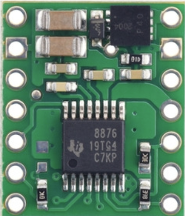
The DRV8876, manufactured by Pololu (Part ID: 4036), is a robust dual H-bridge motor driver designed for driving DC motors and stepper motors. It supports a wide range of operating voltages (up to 36V) and features adjustable current limiting, thermal shutdown, and fault reporting. The device is highly versatile, offering multiple control modes, including PWM for precise speed and torque regulation.
Explore Projects Built with DRV8876

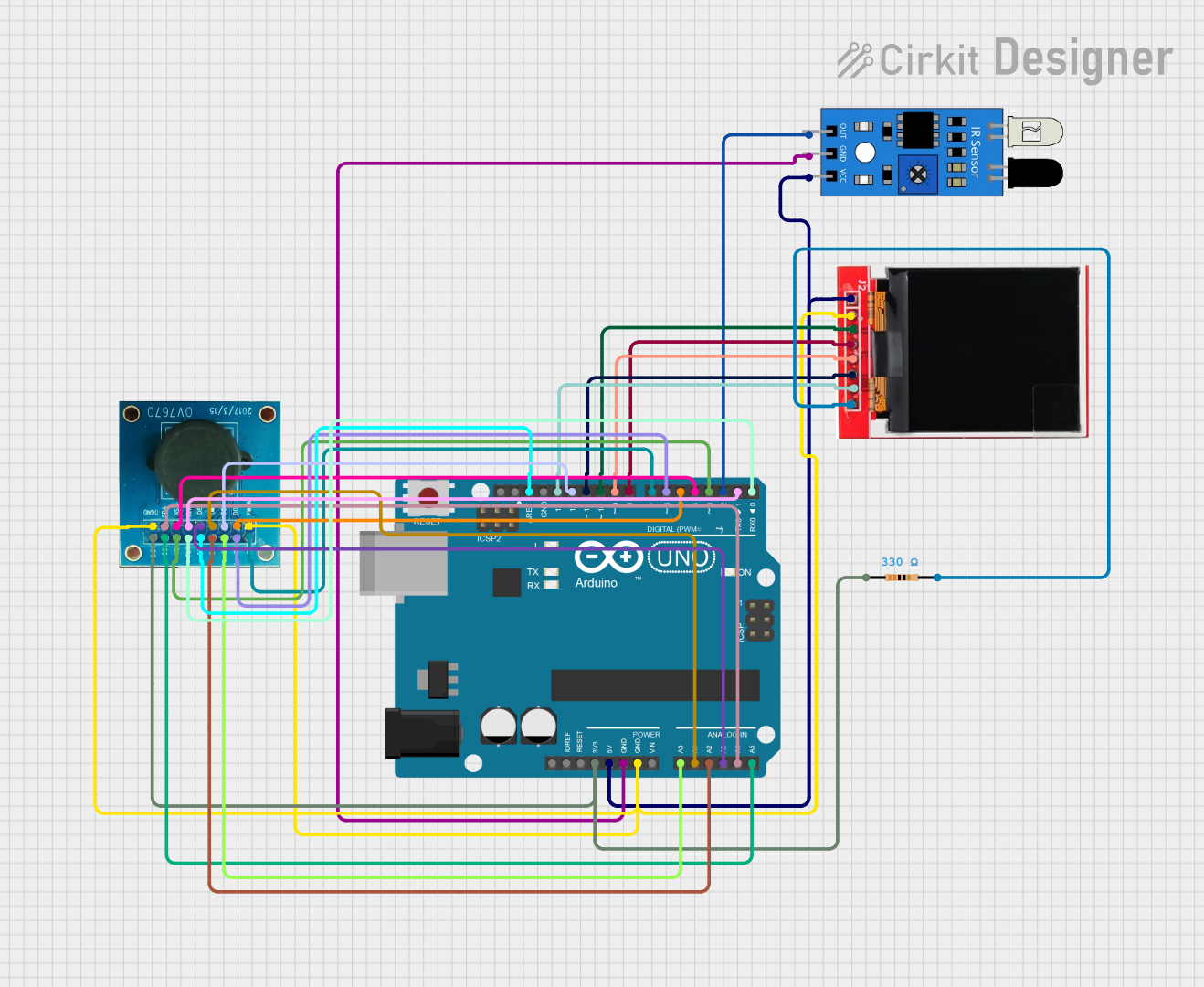

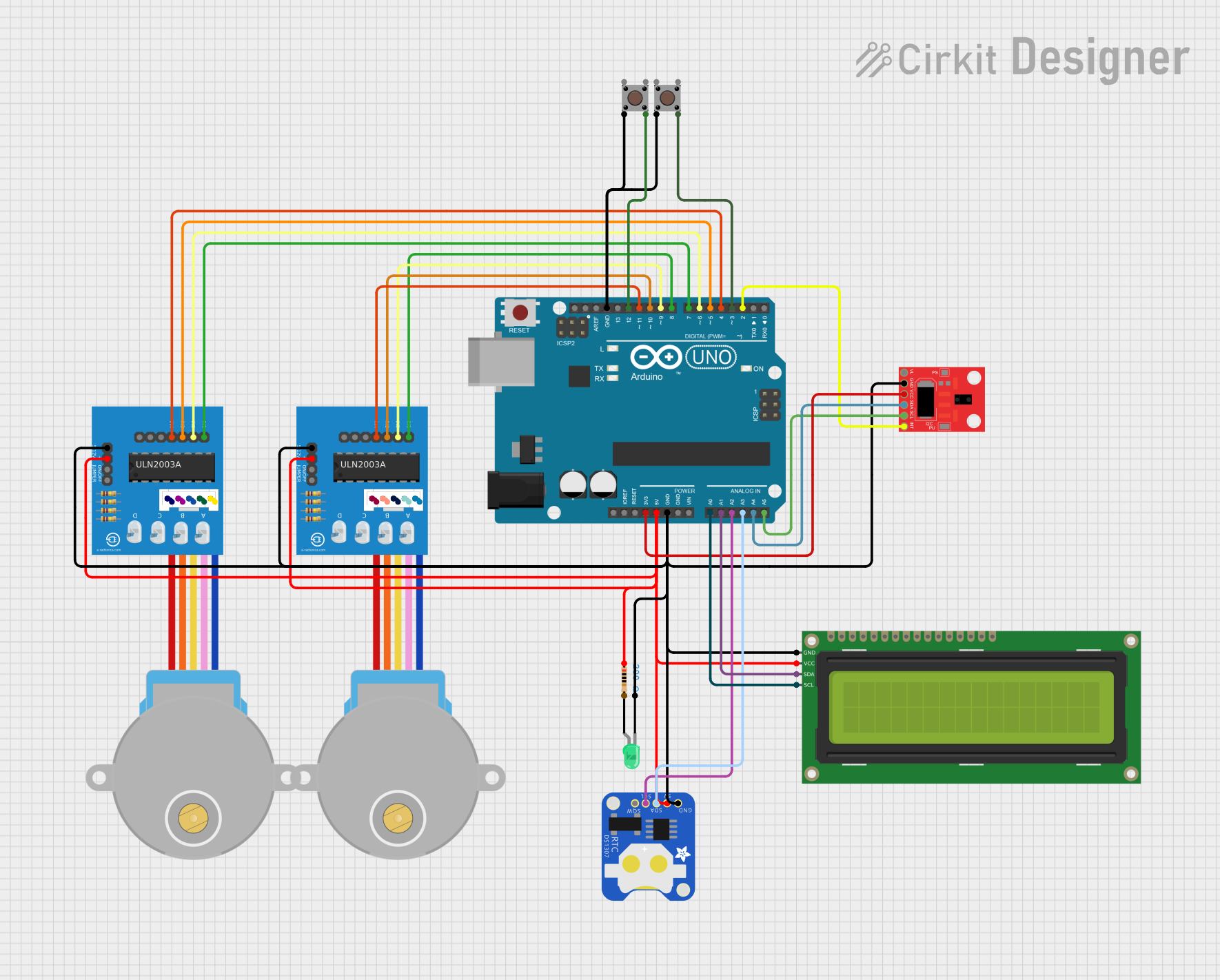
Explore Projects Built with DRV8876
Common Applications
- Robotics: Driving DC motors for wheels, arms, or other actuators.
- Industrial automation: Controlling stepper motors in conveyor belts or CNC machines.
- Consumer electronics: Motorized systems such as fans, pumps, or toys.
- Prototyping: Ideal for use with microcontrollers like Arduino for motor control projects.
Technical Specifications
Key Technical Details
| Parameter | Value |
|---|---|
| Supply Voltage (VM) | 4.5V to 36V |
| Output Current (per H-bridge) | Up to 3.5A (peak), 2A (continuous) |
| Control Modes | PWM, PH/EN, or IN/IN |
| Current Limiting | Adjustable via external resistor |
| Thermal Shutdown | Yes |
| Fault Reporting | Overcurrent, undervoltage, and thermal faults |
| Operating Temperature Range | -40°C to 125°C |
Pin Configuration and Descriptions
The DRV8876 is available in a 16-pin HTSSOP package. Below is the pinout and description:
| Pin Number | Pin Name | Description |
|---|---|---|
| 1 | VM | Motor power supply (4.5V to 36V). Connect a decoupling capacitor to GND. |
| 2 | GND | Ground reference for the device. |
| 3 | IN1 | Input control for H-bridge 1. |
| 4 | IN2 | Input control for H-bridge 2. |
| 5 | nFAULT | Fault output (active low). Indicates fault conditions. |
| 6 | VREF | Reference voltage for current regulation. |
| 7 | ISEN | Current sense pin. Connect a resistor to set current limit. |
| 8 | OUT1 | Output terminal for H-bridge 1. Connect to motor terminal. |
| 9 | OUT2 | Output terminal for H-bridge 2. Connect to motor terminal. |
| 10 | OUT3 | Output terminal for H-bridge 3. Connect to motor terminal. |
| 11 | OUT4 | Output terminal for H-bridge 4. Connect to motor terminal. |
| 12 | nSLEEP | Sleep mode input (active low). Pull high to enable the device. |
| 13 | PH/EN | Phase/Enable control input (optional, depends on control mode). |
| 14 | PWM | PWM input for speed control (optional, depends on control mode). |
| 15 | VCC | Logic power supply (3.3V or 5V). |
| 16 | NC | No connection. Leave unconnected. |
Usage Instructions
Using the DRV8876 in a Circuit
- Power Supply: Connect the motor power supply (VM) to the VM pin. Ensure the voltage is within the range of 4.5V to 36V. Add a decoupling capacitor (e.g., 100 µF) between VM and GND to stabilize the supply.
- Motor Connections: Connect the motor terminals to the OUT1/OUT2 or OUT3/OUT4 pins, depending on the motor configuration.
- Control Inputs:
- For PWM control, connect the PWM signal to the PWM pin and set the PH/EN pin for direction control.
- Alternatively, use the IN1/IN2 pins for IN/IN control mode.
- Current Limiting: Set the current limit by connecting a resistor between the ISEN pin and GND. Use the formula: [ I_{LIMIT} = \frac{V_{REF}}{R_{ISEN}} ] where ( V_{REF} ) is the reference voltage applied to the VREF pin.
- Fault Monitoring: Monitor the nFAULT pin for fault conditions. This pin is active low and can be connected to a microcontroller for fault detection.
- Sleep Mode: Pull the nSLEEP pin high to enable the device. Pull it low to put the device into low-power sleep mode.
Example Arduino Code
Below is an example of how to control a DC motor using the DRV8876 with an Arduino UNO in PWM mode:
// Define pin connections
const int pwmPin = 9;    // PWM signal for speed control
const int dirPin = 8;    // Direction control (PH/EN mode)
const int sleepPin = 7;  // Sleep mode control

void setup() {
  // Set pin modes
  pinMode(pwmPin, OUTPUT);
  pinMode(dirPin, OUTPUT);
  pinMode(sleepPin, OUTPUT);

  // Enable the DRV8876
  digitalWrite(sleepPin, HIGH); // Pull nSLEEP high to enable the driver
}

void loop() {
  // Set motor direction
  digitalWrite(dirPin, HIGH); // Set direction (HIGH or LOW)

  // Set motor speed using PWM
  analogWrite(pwmPin, 128); // 50% duty cycle (range: 0-255)

  delay(2000); // Run motor for 2 seconds

  // Stop the motor
  analogWrite(pwmPin, 0); // Set PWM to 0 to stop the motor

  delay(2000); // Wait for 2 seconds before restarting
}
Best Practices
- Use a heat sink or ensure proper ventilation if operating near the maximum current rating.
- Add a flyback diode across the motor terminals to protect against voltage spikes.
- Use a low ESR capacitor on the VM pin to reduce noise and improve stability.
Troubleshooting and FAQs
Common Issues and Solutions
Motor Not Spinning:
- Ensure the nSLEEP pin is pulled high to enable the device.
- Verify the motor connections to the OUT pins.
- Check the power supply voltage and ensure it is within the specified range.
Overheating:
- Reduce the motor current by adjusting the current limit resistor.
- Ensure proper heat dissipation with a heat sink or cooling fan.
nFAULT Pin is Low:
- Check for overcurrent, undervoltage, or thermal shutdown conditions.
- Verify the motor is not drawing more current than the driver can handle.
PWM Control Not Working:
- Ensure the PWM frequency is within the recommended range (typically 20 kHz).
- Verify the PWM signal is connected to the correct pin.
FAQs
Q: Can the DRV8876 drive two DC motors simultaneously?
A: Yes, the DRV8876 has two H-bridges, allowing it to drive two DC motors independently.
Q: What is the maximum PWM frequency supported?
A: The DRV8876 typically supports PWM frequencies up to 100 kHz, but 20 kHz is recommended for optimal performance.
Q: How do I calculate the current limit resistor value?
A: Use the formula ( R_{ISEN} = \frac{V_{REF}}{I_{LIMIT}} ), where ( V_{REF} ) is the reference voltage applied to the VREF pin.
Q: Can I use the DRV8876 with a 3.3V microcontroller?
A: Yes, the DRV8876 is compatible with both 3.3V and 5V logic levels.
By following this documentation, users can effectively integrate the DRV8876 into their motor control projects.