
How to Use PCA9306: Examples, Pinouts, and Specs
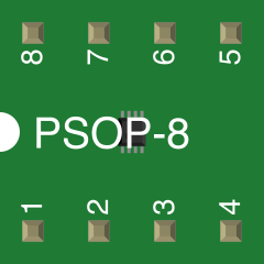
 Design with PCA9306 in Cirkit Designer
Introduction
The PCA9306, manufactured by Texas Instruments, is a dual bidirectional I2C bus buffer designed for level shifting between different voltage levels. It enables seamless communication between devices operating at different I2C voltages, making it an essential component in mixed-voltage systems. The PCA9306 is particularly useful in applications where devices with different logic levels need to communicate over the I2C bus.
Explore Projects Built with PCA9306
 Open Project in Cirkit Designer
 Open Project in Cirkit Designer
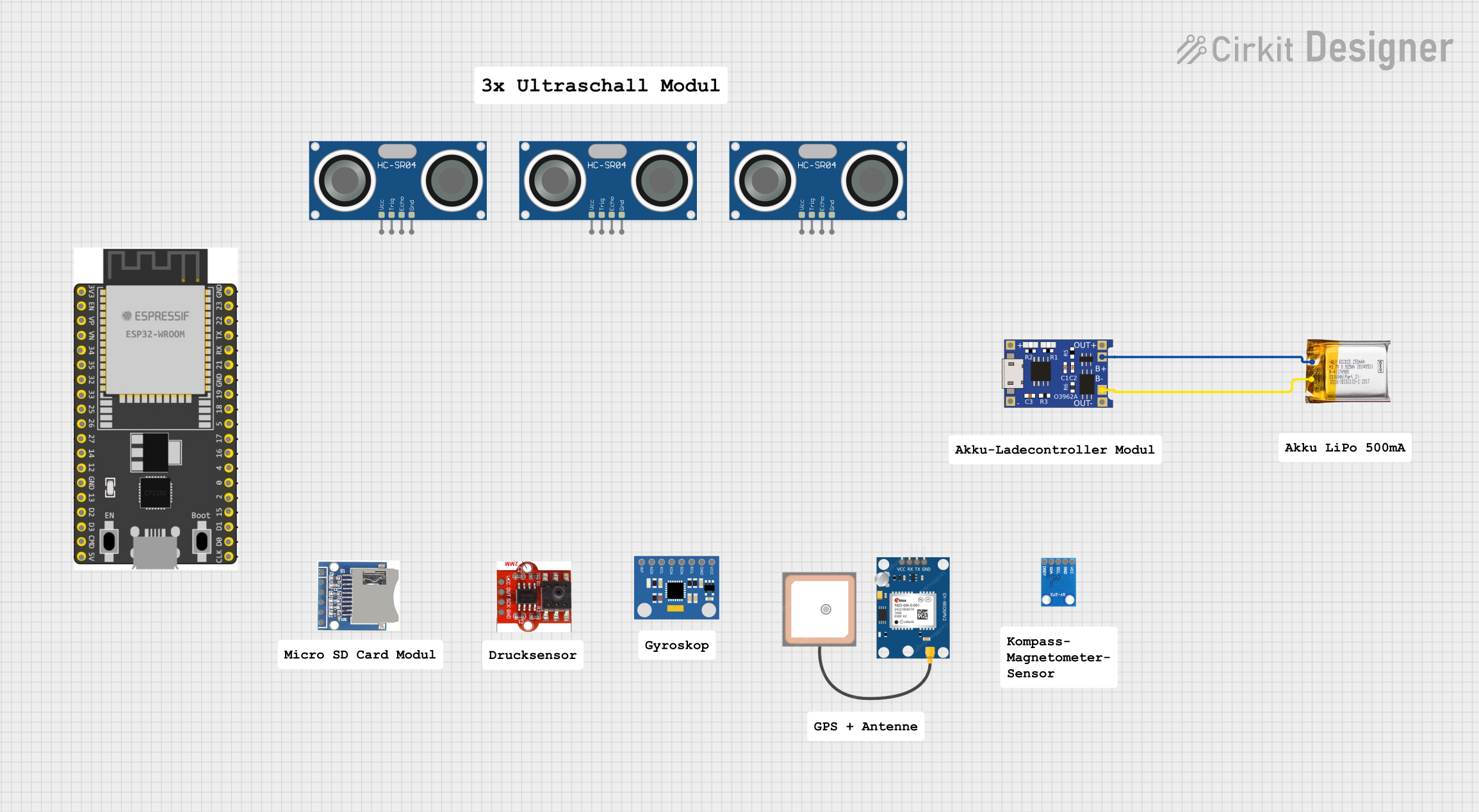 Open Project in Cirkit Designer
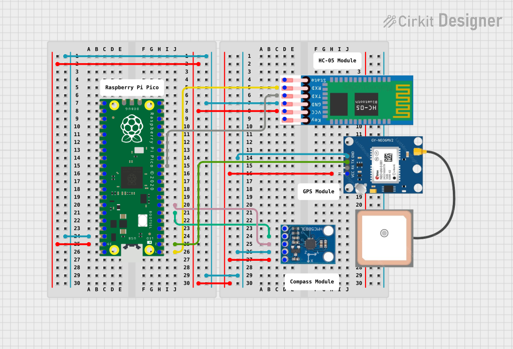 Open Project in Cirkit Designer
Explore Projects Built with PCA9306
Open Project in Cirkit DesignerOpen Project in Cirkit DesignerOpen Project in Cirkit DesignerOpen Project in Cirkit DesignerCommon Applications and Use Cases
- Level shifting for I2C communication between devices with different voltage levels.
- Mixed-voltage system integration in embedded systems.
- Consumer electronics, such as smartphones and tablets.
- Industrial automation and control systems.
- Communication between microcontrollers and peripheral devices like sensors, EEPROMs, and displays.
Technical Specifications
The PCA9306 is a versatile and robust component with the following key technical specifications:
| Parameter | Value |
|---|---|
| Operating Voltage Range | 1.2 V to 5.5 V (VREF1), 1.8 V to 5.5 V (VREF2) |
| Maximum Data Rate | 10 Mbps |
| Operating Temperature Range | -40°C to +85°C |
| I2C Compatibility | Supports Standard-Mode (100 kbps), Fast-Mode (400 kbps), and Fast-Mode Plus (1 Mbps) |
| Input Capacitance | 6 pF (typical) |
| Propagation Delay | 0.3 ns (typical) |
| Package Options | SOT-23-6, VSSOP-8 |
Pin Configuration and Descriptions
The PCA9306 is available in a 6-pin SOT-23 package. Below is the pin configuration and description:
| Pin Name | Pin Number | Description |
|---|---|---|
| VREF1 | 1 | Reference voltage for the lower voltage side of the I2C bus. |
| EN | 2 | Enable pin. Pull high to enable the device. |
| Lx | 3 | Low-voltage side I2C bus connection (SDA/SCL). |
| Hx | 4 | High-voltage side I2C bus connection (SDA/SCL). |
| GND | 5 | Ground connection. |
| VREF2 | 6 | Reference voltage for the higher voltage side of the I2C bus. |
Usage Instructions
How to Use the PCA9306 in a Circuit
Power Supply Connections:
- Connect the lower voltage reference (e.g., 1.8 V) to the
VREF1pin. - Connect the higher voltage reference (e.g., 3.3 V or 5 V) to the
VREF2pin. - Ensure that
VREF2is always greater than or equal toVREF1.
- Connect the lower voltage reference (e.g., 1.8 V) to the
Enable the Device:
- Pull the
ENpin high to enable the PCA9306. If unused, connect it toVREF2.
- Pull the
I2C Bus Connections:
- Connect the low-voltage I2C bus lines (SDA and SCL) to the
Lxpin. - Connect the high-voltage I2C bus lines (SDA and SCL) to the
Hxpin.
- Connect the low-voltage I2C bus lines (SDA and SCL) to the
Pull-Up Resistors:
- Use appropriate pull-up resistors on both the low-voltage and high-voltage sides of the I2C bus. The resistor values depend on the bus capacitance and desired speed.
Bypass Capacitors:
- Place a 0.1 µF decoupling capacitor close to the
VREF1andVREF2pins to ensure stable operation.
- Place a 0.1 µF decoupling capacitor close to the
Important Considerations and Best Practices
- Ensure that the voltage difference between
VREF1andVREF2does not exceed the specified limits. - Avoid leaving the
ENpin floating; always connect it to a defined logic level. - Verify that the pull-up resistor values are appropriate for the desired I2C speed and bus capacitance.
- Keep traces for the I2C lines as short as possible to minimize noise and signal degradation.
Example: Using PCA9306 with Arduino UNO
The PCA9306 can be used to interface an Arduino UNO (5 V logic) with a 3.3 V I2C sensor. Below is an example Arduino code snippet for reading data from a 3.3 V I2C sensor:
#include <Wire.h> // Include the Wire library for I2C communication

void setup() {
  Wire.begin(); // Initialize I2C communication
  Serial.begin(9600); // Start serial communication for debugging
  Serial.println("PCA9306 Level Shifter Example");
}

void loop() {
  Wire.beginTransmission(0x40); // Start communication with the I2C device
  Wire.write(0x00); // Send a command or register address
  Wire.endTransmission(); // End the transmission

  Wire.requestFrom(0x40, 2); // Request 2 bytes of data from the device
  if (Wire.available() == 2) {
    int data = Wire.read() << 8 | Wire.read(); // Read and combine the data
    Serial.print("Sensor Data: ");
    Serial.println(data); // Print the received data
  }

  delay(1000); // Wait for 1 second before the next read
}
Troubleshooting and FAQs
Common Issues and Solutions
No Communication on the I2C Bus:
- Verify that the
ENpin is pulled high. - Check the pull-up resistors on both sides of the I2C bus.
- Ensure that
VREF1andVREF2are powered correctly and within the specified range.
- Verify that the
Data Corruption or Noise:
- Use shorter traces for the I2C lines to reduce noise.
- Add bypass capacitors near the power supply pins.
- Verify that the pull-up resistor values are appropriate for the bus speed.
Device Overheating:
- Ensure that the voltage difference between
VREF1andVREF2does not exceed the maximum rating. - Check for any short circuits on the PCB.
- Ensure that the voltage difference between
FAQs
Q1: Can the PCA9306 be used for SPI communication?
A1: No, the PCA9306 is specifically designed for I2C communication and is not suitable for SPI.
Q2: What is the maximum voltage difference allowed between VREF1 and VREF2?
A2: The voltage difference between VREF1 and VREF2 must not exceed 5.5 V.
Q3: Do I need pull-up resistors on both sides of the I2C bus?
A3: Yes, pull-up resistors are required on both the low-voltage and high-voltage sides of the I2C bus for proper operation.
Q4: Can the PCA9306 operate at 1 Mbps I2C speed?
A4: Yes, the PCA9306 supports Fast-Mode Plus (1 Mbps) I2C communication. Ensure proper pull-up resistor values for high-speed operation.