How to Use ESP32 CAM WROVER: Examples, Pinouts, and Specs
Introduction
The ESP32 CAM WROVER is a compact development board manufactured by ESP32, featuring the powerful ESP32 chip. It integrates a camera module, Wi-Fi, and Bluetooth capabilities, making it an excellent choice for IoT applications, image processing, and wireless communication projects. Its small form factor and versatile features make it ideal for projects such as home automation, surveillance systems, and AI-based image recognition.
Explore Projects Built with ESP32 CAM WROVER


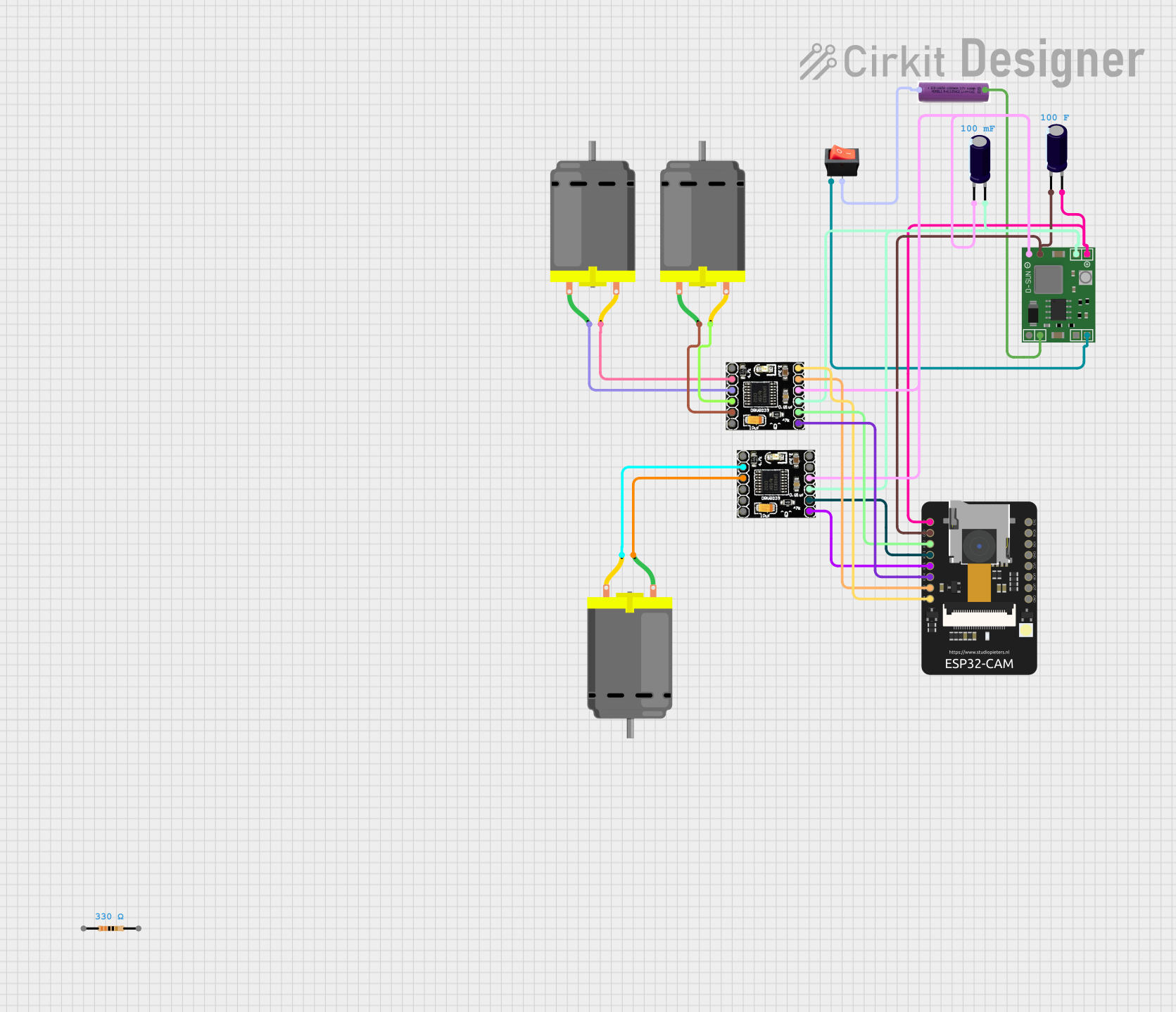
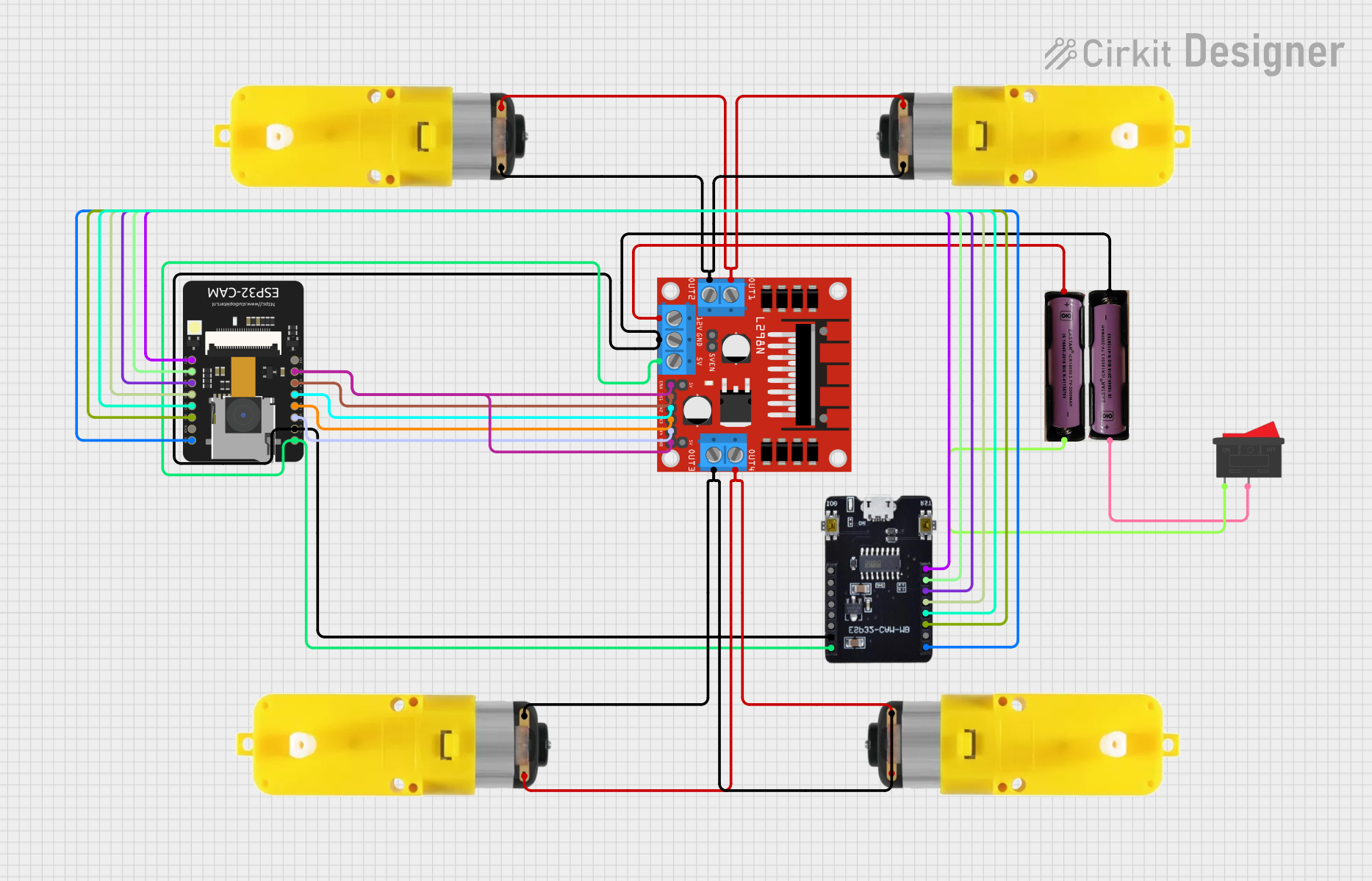
Explore Projects Built with ESP32 CAM WROVER
Common Applications and Use Cases
- Smart home devices and automation
- Wireless surveillance cameras
- Face and object recognition systems
- IoT-enabled image processing
- Remote monitoring and control
- AI and machine learning applications
Technical Specifications
The ESP32 CAM WROVER is designed to deliver high performance in a compact package. Below are its key technical specifications:
| Specification | Details |
|---|---|
| Microcontroller | ESP32-D0WD |
| Flash Memory | 4 MB (SPI Flash) |
| PSRAM | 8 MB |
| Camera Module | OV2640 (2 MP resolution) |
| Wi-Fi | 802.11 b/g/n |
| Bluetooth | Bluetooth 4.2 (BLE and Classic) |
| Operating Voltage | 3.3V |
| Input Voltage Range | 5V (via external power supply or USB) |
| GPIO Pins | 9 GPIO pins available for user applications |
| Interfaces | UART, SPI, I2C, PWM, ADC |
| Dimensions | 27 mm x 40.5 mm |
| Power Consumption | 180 mA (average during operation) |
| Camera Features | Support for JPEG, BMP, and grayscale image formats |
| Operating Temperature | -20°C to 85°C |
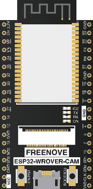
Pin Configuration and Descriptions
The ESP32 CAM WROVER has a total of 16 pins. Below is the pinout and description:
| Pin | Name | Description |
|---|---|---|
| 1 | GND | Ground connection |
| 2 | 3.3V | 3.3V power supply output |
| 3 | IO0 | GPIO0, used for boot mode selection (connect to GND for programming) |
| 4 | IO1 | GPIO1, general-purpose I/O |
| 5 | IO2 | GPIO2, general-purpose I/O |
| 6 | IO3 | GPIO3, general-purpose I/O |
| 7 | IO4 | GPIO4, general-purpose I/O |
| 8 | IO5 | GPIO5, general-purpose I/O |
| 9 | TXD | UART TX pin |
| 10 | RXD | UART RX pin |
| 11 | GND | Ground connection |
| 12 | 5V | 5V power input |
| 13 | IO12 | GPIO12, general-purpose I/O |
| 14 | IO13 | GPIO13, general-purpose I/O |
| 15 | IO14 | GPIO14, general-purpose I/O |
| 16 | IO15 | GPIO15, general-purpose I/O |
Usage Instructions
The ESP32 CAM WROVER is versatile and easy to use in a variety of projects. Below are the steps to get started:
Setting Up the ESP32 CAM WROVER
- Power Supply: Connect a 5V power source to the 5V pin or use a USB-to-serial adapter for programming.
- Programming Mode: To upload code, connect GPIO0 to GND and reset the board.
- Camera Configuration: Ensure the OV2640 camera module is securely connected to the board.
- Development Environment: Use the Arduino IDE or ESP-IDF for programming. Install the ESP32 board package in the Arduino IDE.
Example Code: Capturing an Image
Below is an example Arduino sketch to capture an image using the ESP32 CAM WROVER:
#include "esp_camera.h"

// Camera pin configuration for ESP32 CAM WROVER
#define PWDN_GPIO_NUM    -1 // Power down pin, not used
#define RESET_GPIO_NUM   -1 // Reset pin, not used
#define XCLK_GPIO_NUM     0 // XCLK pin
#define SIOD_GPIO_NUM    26 // SIOD pin
#define SIOC_GPIO_NUM    27 // SIOC pin
#define Y9_GPIO_NUM      35 // Y9 pin
#define Y8_GPIO_NUM      34 // Y8 pin
#define Y7_GPIO_NUM      39 // Y7 pin
#define Y6_GPIO_NUM      36 // Y6 pin
#define Y5_GPIO_NUM      21 // Y5 pin
#define Y4_GPIO_NUM      19 // Y4 pin
#define Y3_GPIO_NUM      18 // Y3 pin
#define Y2_GPIO_NUM       5 // Y2 pin
#define VSYNC_GPIO_NUM   25 // VSYNC pin
#define HREF_GPIO_NUM    23 // HREF pin
#define PCLK_GPIO_NUM    22 // PCLK pin

void setup() {
  Serial.begin(115200);

  // Camera configuration
  camera_config_t config;
  config.ledc_channel = LEDC_CHANNEL_0;
  config.ledc_timer = LEDC_TIMER_0;
  config.pin_d0 = Y2_GPIO_NUM;
  config.pin_d1 = Y3_GPIO_NUM;
  config.pin_d2 = Y4_GPIO_NUM;
  config.pin_d3 = Y5_GPIO_NUM;
  config.pin_d4 = Y6_GPIO_NUM;
  config.pin_d5 = Y7_GPIO_NUM;
  config.pin_d6 = Y8_GPIO_NUM;
  config.pin_d7 = Y9_GPIO_NUM;
  config.pin_xclk = XCLK_GPIO_NUM;
  config.pin_pclk = PCLK_GPIO_NUM;
  config.pin_vsync = VSYNC_GPIO_NUM;
  config.pin_href = HREF_GPIO_NUM;
  config.pin_sscb_sda = SIOD_GPIO_NUM;
  config.pin_sscb_scl = SIOC_GPIO_NUM;
  config.pin_pwdn = PWDN_GPIO_NUM;
  config.pin_reset = RESET_GPIO_NUM;
  config.xclk_freq_hz = 20000000;
  config.pixel_format = PIXFORMAT_JPEG;

  // Initialize the camera
  if (esp_camera_init(&config) != ESP_OK) {
    Serial.println("Camera initialization failed!");
    return;
  }
  Serial.println("Camera initialized successfully.");
}

void loop() {
  // Capture an image
  camera_fb_t *fb = esp_camera_fb_get();
  if (!fb) {
    Serial.println("Failed to capture image.");
    return;
  }

  Serial.println("Image captured successfully.");
  esp_camera_fb_return(fb); // Return the frame buffer to free memory
  delay(5000); // Wait 5 seconds before capturing the next image
}
Important Considerations
- Ensure the power supply provides sufficient current (at least 500 mA) to avoid instability.
- Use a heat sink if the board overheats during prolonged use.
- Avoid connecting GPIO0 to GND during normal operation; it is only required for programming.
Troubleshooting and FAQs
Common Issues
Camera Initialization Failed:
- Ensure the camera module is properly connected.
- Verify the pin configuration in the code matches your hardware setup.
Board Not Detected by Computer:
- Check the USB-to-serial adapter connection.
- Ensure GPIO0 is connected to GND during programming.
Image Capture Fails:
- Verify sufficient power supply to the board.
- Check for loose connections or damaged camera modules.
Solutions and Tips
- Use a high-quality USB cable for programming and power.
- If the board resets frequently, add a capacitor (e.g., 100 µF) across the power supply pins.
- Update the ESP32 board package in the Arduino IDE to the latest version for compatibility.
By following this documentation, you can effectively utilize the ESP32 CAM WROVER for your IoT and image processing projects.