How to Use ESP8266 ESP-12E WiFi Module: Examples, Pinouts, and Specs
Introduction
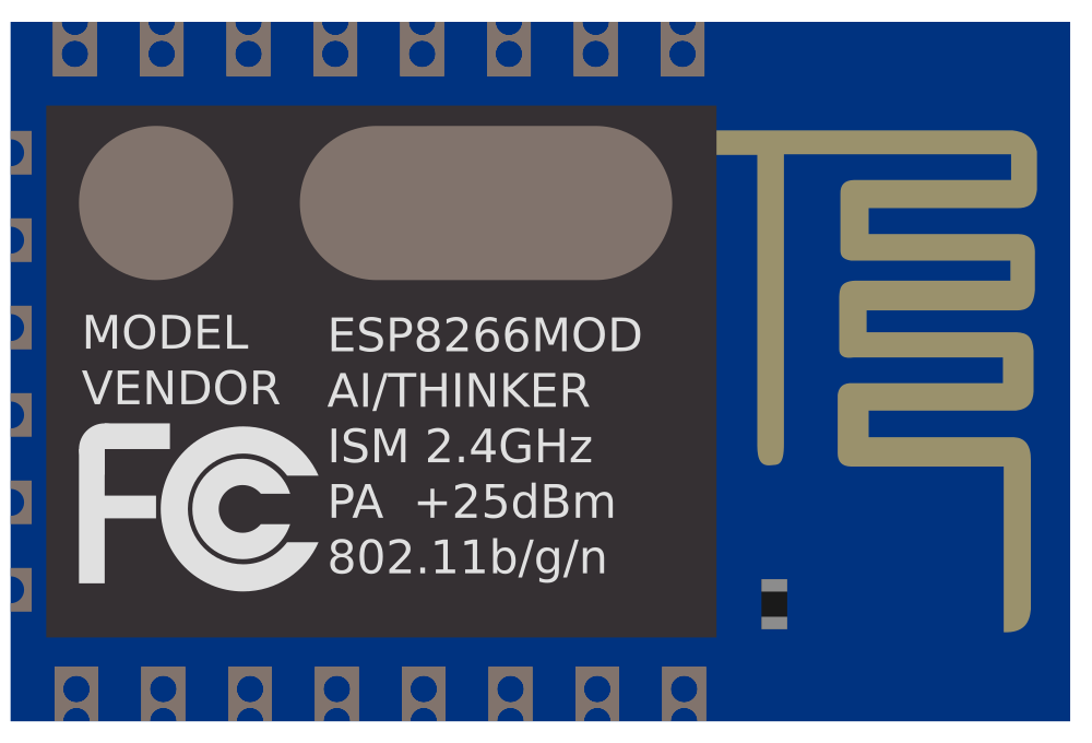
The ESP8266 ESP-12E WiFi Module is a self-contained Wi-Fi networking solution, offering a high degree of integration and robustness. It is designed for space and power-constrained devices, making it ideal for internet of things (IoT) applications. The module can be used for adding wireless capabilities to existing devices or for building standalone networked devices.
Explore Projects Built with ESP8266 ESP-12E WiFi Module
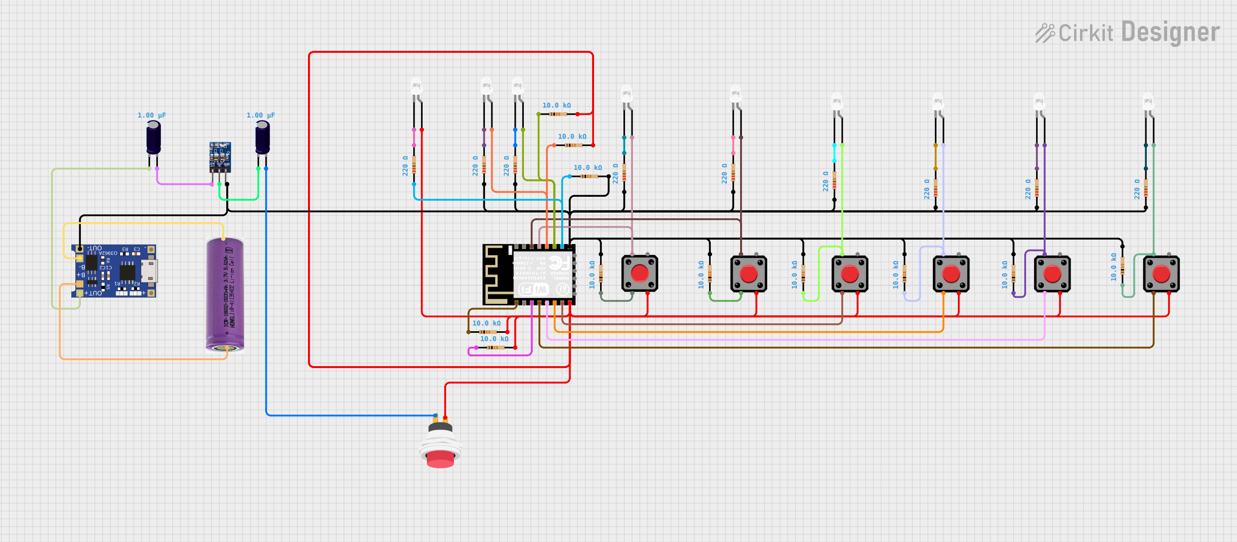
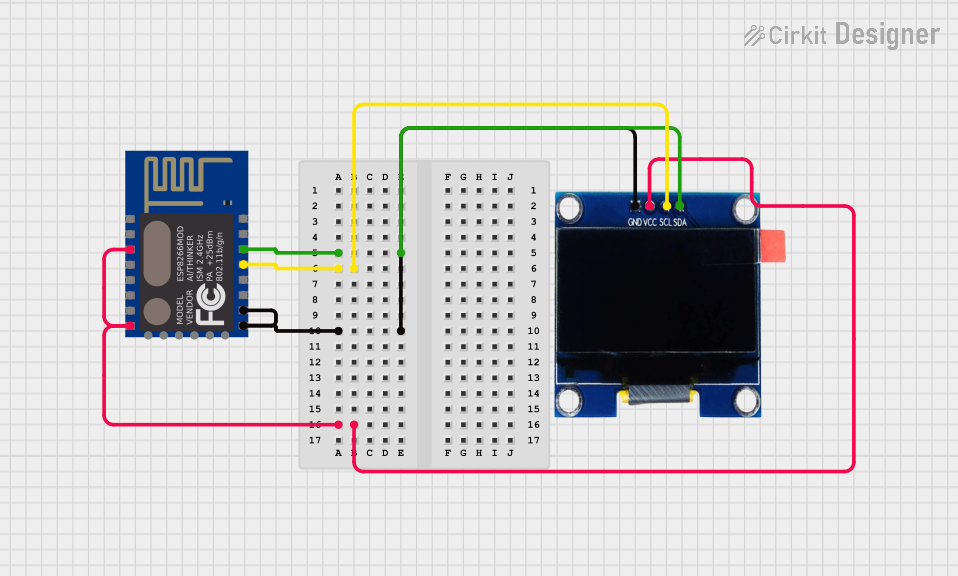
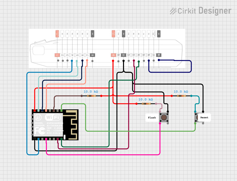

Explore Projects Built with ESP8266 ESP-12E WiFi Module
Common Applications and Use Cases
- Smart home devices
- Wireless sensor networks
- IoT applications
- Wi-Fi enabled switches and controllers
- Remote data logging and monitoring
Technical Specifications
Key Technical Details
- Operating Voltage: 3.0V to 3.6V
- Recommended Operating Voltage: 3.3V
- Operating Current: Average ~80mA
- Wireless Standard: 802.11 b/g/n
- Frequency Range: 2.4 GHz - 2.5 GHz (2400M - 2483.5M)
- Integrated TCP/IP protocol stack
- Flash Memory: 4MB
- Operating Temperature: -40°C to 125°C
Pin Configuration and Descriptions
| Pin Number | Name | Function |
|---|---|---|
| 1 | VCC | Power supply (3.3V) |
| 2 | GND | Ground |
| 3 | TXD | Transmit Data (TX) |
| 4 | RXD | Receive Data (RX) |
| 5 | CH_PD | Chip Power-down (Active high) |
| 6 | GPIO2 | General Purpose I/O |
| 7 | GPIO0 | General Purpose I/O (Flash mode if pulled LOW) |
| 8 | RST | Reset (Active low) |
| 9 | GPIO15 | General Purpose I/O (Boot from SD card if pulled LOW) |
| 10 | GPIO13 | General Purpose I/O |
| 11 | GPIO12 | General Purpose I/O |
| 12 | GPIO14 | General Purpose I/O |
| 13 | GPIO16 | General Purpose I/O (Wake up from deep sleep if connected to RST) |
| 14 | ADC0 | Analog to Digital Converter input |
Usage Instructions
How to Use the Component in a Circuit
- Power Supply: Connect the VCC pin to a 3.3V power source and the GND pin to ground.
- Serial Communication: Connect the TXD and RXD pins to a serial adapter or microcontroller to communicate with the module.
- GPIO Pins: Utilize the GPIO pins for input/output operations. Ensure that GPIO0 is pulled HIGH during normal operation.
- Programming Mode: To flash the module, pull GPIO0 LOW, reset the module, and then proceed with uploading the firmware.
- Reset: Connect a pushbutton to the RST pin for manual resetting or drive it LOW through a microcontroller to reset the module programmatically.
Important Considerations and Best Practices
- Always use a 3.3V power supply to avoid damaging the module.
- Use a logic level converter if interfacing with 5V logic microcontrollers.
- Ensure that the CH_PD pin is connected to VCC to enable the chip.
- Avoid drawing power for other components directly from the module's VCC pin.
- Use proper decoupling capacitors close to the module's power pins to minimize power supply noise.
Example Code for Arduino UNO
#include <ESP8266WiFi.h>

const char* ssid = "yourSSID"; // Replace with your network SSID
const char* password = "yourPASSWORD"; // Replace with your network password

void setup() {
  Serial.begin(115200);
  WiFi.begin(ssid, password);

  while (WiFi.status() != WL_CONNECTED) {
    delay(500);
    Serial.print(".");
  }

  Serial.println("");
  Serial.println("WiFi connected");
  Serial.println("IP address: ");
  Serial.println(WiFi.localIP());
}

void loop() {
  // Your code here
}
Troubleshooting and FAQs
Common Issues Users Might Face
- Module not responding: Ensure that the power supply is 3.3V and that the CH_PD pin is pulled HIGH.
- Cannot connect to Wi-Fi: Check the SSID and password, and ensure the module is within the range of the Wi-Fi router.
- Serial communication errors: Verify that the baud rate matches between the module and the microcontroller.
Solutions and Tips for Troubleshooting
- If the module is not booting, check the GPIO0, GPIO2, and GPIO15 pin states.
- For power issues, ensure that the power supply can deliver sufficient current (up to 300mA during Wi-Fi transmission).
- Use external antennas if the Wi-Fi signal strength is weak.
FAQs
Q: Can the ESP8266 ESP-12E be used with a 5V power supply? A: No, it requires a 3.3V power supply. Using 5V can damage the module.
Q: How do I flash new firmware onto the ESP8266 ESP-12E? A: To flash the firmware, pull GPIO0 LOW, reset the module, and use a serial adapter to upload the firmware.
Q: Can I use the ESP8266 ESP-12E with Arduino IDE? A: Yes, the Arduino IDE supports the ESP8266 with the installation of the appropriate board manager.
Q: What is the maximum range of the Wi-Fi connection? A: The range depends on several factors, including the environment and antenna used, but typically it is around 100 meters in open space.
This documentation provides an overview of the ESP8266 ESP-12E WiFi Module, its technical specifications, usage instructions, example code for Arduino UNO, and troubleshooting tips. For more detailed information, refer to the datasheet and technical references provided by the manufacturer.