
How to Use Power Module GM V1.0: Examples, Pinouts, and Specs
 Design with Power Module GM V1.0 in Cirkit Designer
Introduction
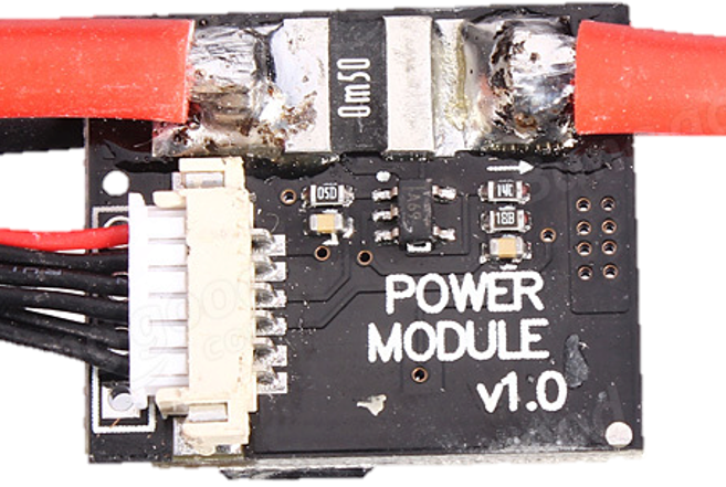
The Power Module GM V1.0 is a compact and versatile power supply module designed to provide stable voltage and current for a wide range of electronic projects. It features adjustable output settings, overcurrent protection, and a user-friendly design, making it an essential component for hobbyists, students, and professionals alike. This module is ideal for powering microcontrollers, sensors, and other low-power devices in prototyping and development environments.
Explore Projects Built with Power Module GM V1.0
 Open Project in Cirkit Designer
 Open Project in Cirkit Designer
 Open Project in Cirkit Designer
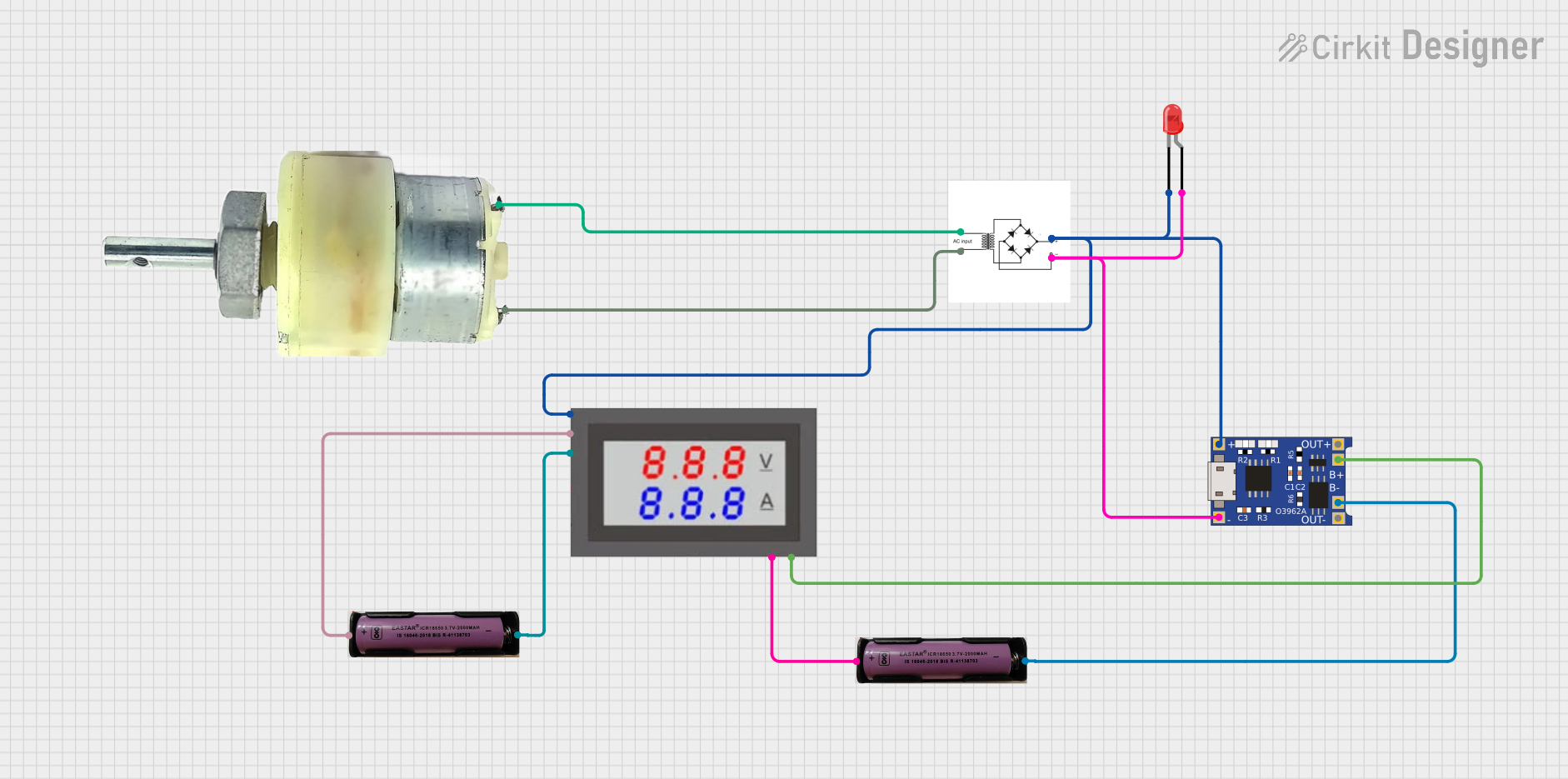 Open Project in Cirkit Designer
Explore Projects Built with Power Module GM V1.0
Open Project in Cirkit DesignerOpen Project in Cirkit DesignerOpen Project in Cirkit DesignerOpen Project in Cirkit DesignerCommon Applications and Use Cases
- Powering Arduino, Raspberry Pi, and other microcontroller boards
- Supplying stable voltage to sensors and actuators
- Prototyping circuits requiring adjustable voltage levels
- Educational and DIY electronics projects
- Bench power supply for small-scale testing
Technical Specifications
Below are the key technical details of the Power Module GM V1.0:
| Parameter | Specification |
|---|---|
| Input Voltage Range | 6V to 24V DC |
| Output Voltage Range | 3.3V to 12V DC (adjustable) |
| Maximum Output Current | 2A |
| Efficiency | Up to 95% |
| Protection Features | Overcurrent, short-circuit, thermal |
| Dimensions | 45mm x 25mm x 15mm |
| Weight | 10g |
Pin Configuration and Descriptions
The Power Module GM V1.0 has the following pin layout:
| Pin Name | Description |
|---|---|
| VIN | Input voltage pin (6V to 24V DC) |
| GND | Ground pin (common ground for input and output) |
| VOUT | Adjustable output voltage pin (3.3V to 12V DC) |
| ADJ | Voltage adjustment pin (used with a potentiometer) |
Usage Instructions
How to Use the Power Module GM V1.0 in a Circuit
Connect Input Voltage:
- Connect a DC power source (6V to 24V) to the
VINpin andGNDpin. - Ensure the input voltage is within the specified range to avoid damage.
- Connect a DC power source (6V to 24V) to the
Adjust Output Voltage:
- Use the onboard potentiometer connected to the
ADJpin to set the desired output voltage. - Measure the output voltage at the
VOUTpin using a multimeter for precise adjustment.
- Use the onboard potentiometer connected to the
Connect the Load:
- Connect the device or circuit to be powered to the
VOUTandGNDpins. - Ensure the load does not exceed the maximum output current of 2A.
- Connect the device or circuit to be powered to the
Power On:
- Turn on the input power supply and verify the output voltage and current.
Important Considerations and Best Practices
- Always verify the input and output voltage levels before connecting sensitive devices.
- Avoid exceeding the maximum input voltage (24V) or output current (2A) to prevent damage.
- Use proper heat dissipation methods if the module operates at high currents for extended periods.
- Ensure proper polarity when connecting the input and output terminals.
Example: Using Power Module GM V1.0 with Arduino UNO
The Power Module GM V1.0 can be used to power an Arduino UNO. Below is an example setup:
- Connect a 12V DC power source to the
VINandGNDpins of the module. - Adjust the output voltage to 5V using the potentiometer.
- Connect the
VOUTpin of the module to the5Vpin of the Arduino UNO. - Connect the
GNDpin of the module to theGNDpin of the Arduino UNO.
Here is a simple Arduino code example to blink an LED while powered by the module:
// Simple LED Blink Example
// Ensure the Power Module GM V1.0 is set to 5V output for Arduino UNO

const int ledPin = 13; // Built-in LED pin on Arduino UNO

void setup() {
  pinMode(ledPin, OUTPUT); // Set the LED pin as an output
}

void loop() {
  digitalWrite(ledPin, HIGH); // Turn the LED on
  delay(1000);               // Wait for 1 second
  digitalWrite(ledPin, LOW);  // Turn the LED off
  delay(1000);               // Wait for 1 second
}
Troubleshooting and FAQs
Common Issues and Solutions
No Output Voltage:
- Verify that the input voltage is within the specified range (6V to 24V).
- Check all connections for proper polarity and secure contact.
- Ensure the potentiometer is not set to the minimum output voltage.
Output Voltage is Unstable:
- Check if the input power supply is stable and capable of providing sufficient current.
- Ensure the load does not exceed the maximum output current of 2A.
- Inspect the module for overheating and provide adequate ventilation if necessary.
Module Overheats:
- Reduce the load current if it exceeds 2A.
- Use a heatsink or active cooling to dissipate heat during high-current operation.
Short Circuit Protection Triggered:
- Disconnect the load and inspect for short circuits in the connected circuit.
- Reset the module by removing and reapplying the input power.
Frequently Asked Questions
Q1: Can the module output 5V for USB-powered devices?
A1: Yes, the module can be adjusted to output 5V, making it suitable for USB-powered devices.
Q2: Is the module suitable for battery-powered applications?
A2: Yes, the module can be used with batteries as long as the input voltage is within the 6V to 24V range.
Q3: Can I use this module to power multiple devices simultaneously?
A3: Yes, as long as the total current draw does not exceed 2A and the devices share a common ground.
Q4: Does the module have reverse polarity protection?
A4: No, the module does not have built-in reverse polarity protection. Ensure correct polarity when connecting the input voltage.
By following this documentation, users can effectively integrate the Power Module GM V1.0 into their projects and troubleshoot common issues with ease.