
Cirkit Designer
Your all-in-one circuit design IDE
Home /
Component Documentation
How to Use Fan - Ventilator: Examples, Pinouts, and Specs
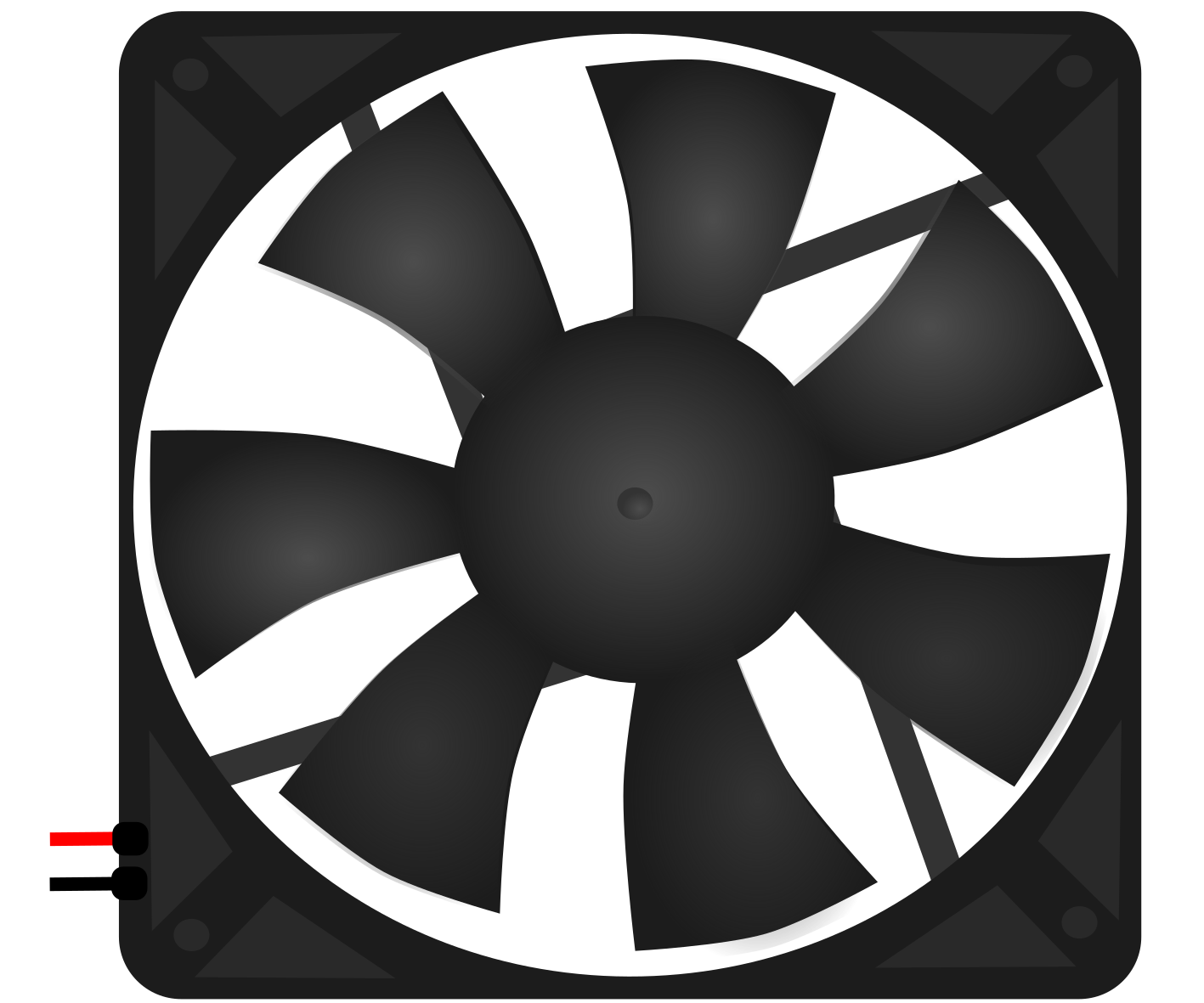
 Design with Fan - Ventilator in Cirkit Designer
Introduction
- A fan or ventilator is an electromechanical device used to create airflow by converting electrical energy into mechanical motion. It typically consists of a motor and blades that rotate to move air.
- Common applications include cooling electronic devices (e.g., computers, power supplies), ventilation in HVAC systems, and air circulation in appliances or industrial setups.
Explore Projects Built with Fan - Ventilator
Battery-Powered IR Sensor Controlled Fan with LED Indicator
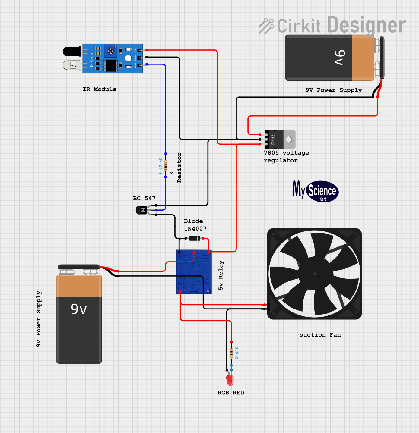
This circuit is a fan control system that uses an IR sensor to detect motion and activate a relay, which in turn powers a fan. The circuit includes a voltage regulator to step down the voltage from a 9V battery to 5V, and an NPN transistor to control the relay coil, with an LED indicator to show the status of the fan.
Open Project in Cirkit DesignerMQ-4 Gas Sensor Controlled Exhaust Fan System
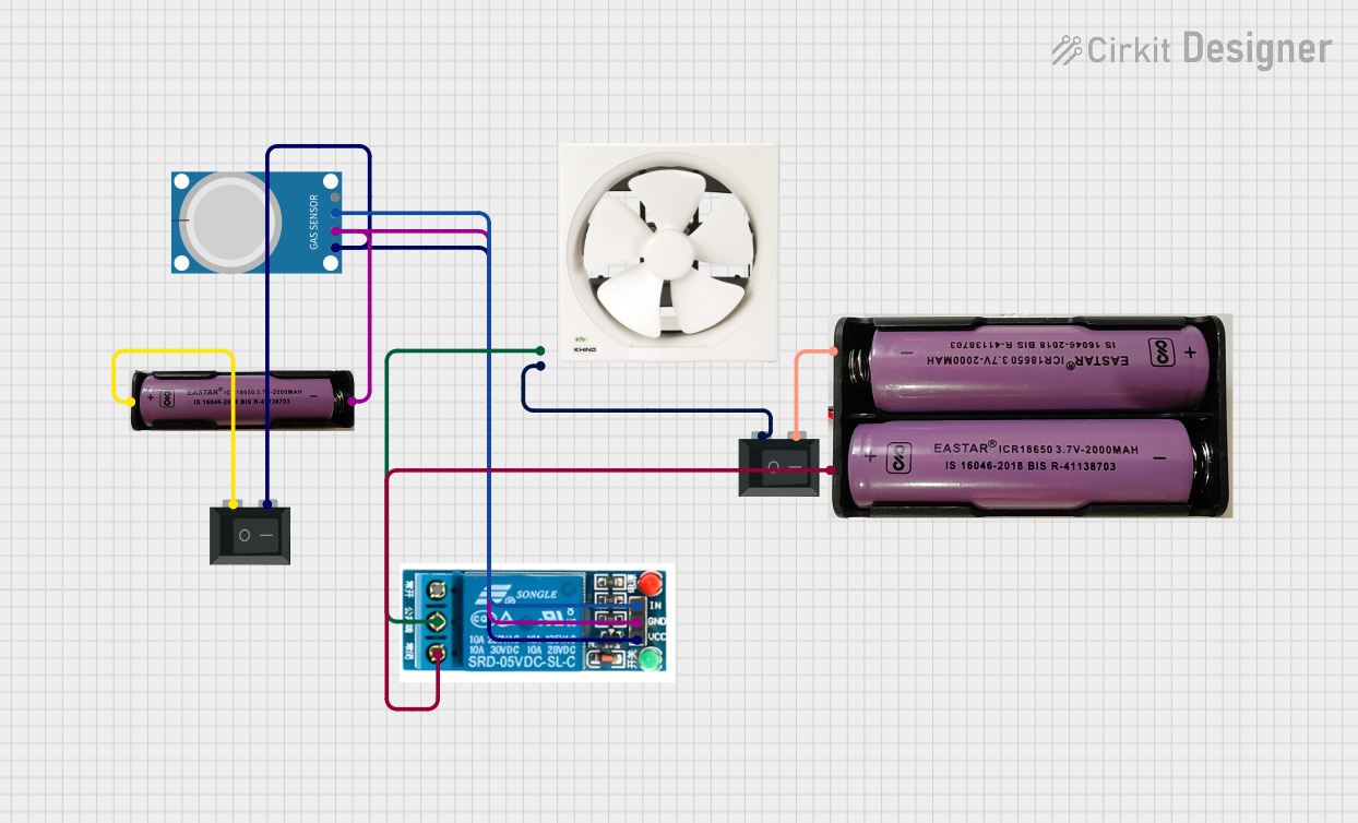
This circuit features an MQ-4 gas sensor connected to a 5V relay, which likely controls the activation of an exhaust fan based on the gas concentration levels detected. The relay switches power from a 7.4V source to the fan, with two rocker switches acting as manual on/off controls for the power supply to the relay and the fan. The circuit is designed to provide safety by automatically activating ventilation when potentially dangerous gas levels are detected.
Open Project in Cirkit DesignerArduino UNO-Based Smart Fan Control System with Bluetooth and Temperature Sensor
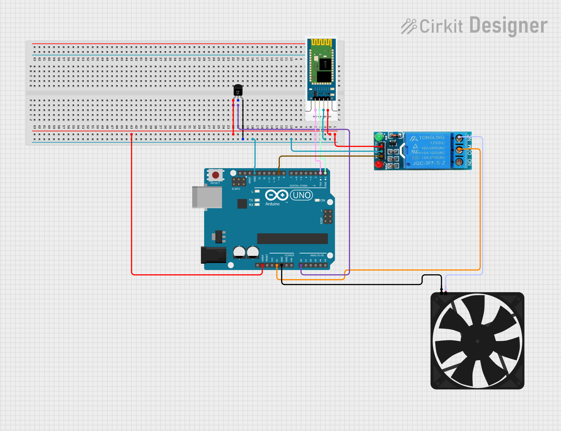
This circuit is a temperature-controlled fan system using an Arduino UNO, an LM35 temperature sensor, and a relay module. The Arduino reads the temperature from the LM35 sensor and controls the fan via the relay based on a predefined temperature threshold, with the option for manual override through Bluetooth commands using an HC-06 module.
Open Project in Cirkit DesignerArduino UNO Temperature-Based Fan Speed Control with LCD Display and LED Alert
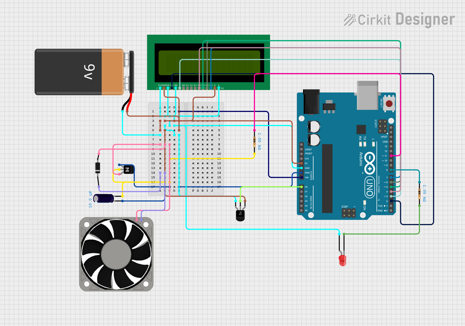
This circuit is a temperature-based fan speed control and monitoring system. It uses an LM35 temperature sensor to read the ambient temperature, an Arduino UNO to process the data and control the fan speed via a transistor, and a 16x2 LCD to display the temperature and fan speed. An LED is also included to indicate when the temperature exceeds a maximum threshold.
Open Project in Cirkit DesignerExplore Projects Built with Fan - Ventilator
Battery-Powered IR Sensor Controlled Fan with LED Indicator
This circuit is a fan control system that uses an IR sensor to detect motion and activate a relay, which in turn powers a fan. The circuit includes a voltage regulator to step down the voltage from a 9V battery to 5V, and an NPN transistor to control the relay coil, with an LED indicator to show the status of the fan.
Open Project in Cirkit DesignerMQ-4 Gas Sensor Controlled Exhaust Fan System
This circuit features an MQ-4 gas sensor connected to a 5V relay, which likely controls the activation of an exhaust fan based on the gas concentration levels detected. The relay switches power from a 7.4V source to the fan, with two rocker switches acting as manual on/off controls for the power supply to the relay and the fan. The circuit is designed to provide safety by automatically activating ventilation when potentially dangerous gas levels are detected.
Open Project in Cirkit DesignerArduino UNO-Based Smart Fan Control System with Bluetooth and Temperature Sensor
This circuit is a temperature-controlled fan system using an Arduino UNO, an LM35 temperature sensor, and a relay module. The Arduino reads the temperature from the LM35 sensor and controls the fan via the relay based on a predefined temperature threshold, with the option for manual override through Bluetooth commands using an HC-06 module.
Open Project in Cirkit DesignerArduino UNO Temperature-Based Fan Speed Control with LCD Display and LED Alert
This circuit is a temperature-based fan speed control and monitoring system. It uses an LM35 temperature sensor to read the ambient temperature, an Arduino UNO to process the data and control the fan speed via a transistor, and a 16x2 LCD to display the temperature and fan speed. An LED is also included to indicate when the temperature exceeds a maximum threshold.
Open Project in Cirkit DesignerTechnical Specifications
- Voltage Range: 5V to 24V DC (varies by model)
- Current Consumption: 0.1A to 1A (depending on size and load)
- Power Rating: 0.5W to 24W
- Speed: 1000 to 5000 RPM (Revolutions Per Minute)
- Airflow: 10 to 200 CFM (Cubic Feet per Minute)
- Noise Level: 20 to 50 dBA
- Operating Temperature: -10°C to 70°C
- Lifespan: 30,000 to 100,000 hours (depending on quality and usage)
Pin Configuration and Descriptions
| Pin Number | Pin Name | Description |
|---|---|---|
| 1 | VCC (+) | Positive power supply input. Connect to the rated voltage (e.g., 12V DC). |
| 2 | GND (-) | Ground connection. Connect to the circuit's ground. |
| 3 | Tachometer (T) | Optional. Outputs a pulse signal proportional to the fan's speed (RPM). |
| 4 | PWM (optional) | Optional. Used for speed control via Pulse Width Modulation (PWM) signal. |
Note: Some fans may only have two pins (VCC and GND) or three pins (VCC, GND, and Tachometer). Check your specific model for details.
Usage Instructions
Connecting the Fan:
- Identify the fan's voltage rating (e.g., 12V DC) and ensure your power supply matches this rating.
- Connect the VCC pin to the positive terminal of the power supply.
- Connect the GND pin to the ground terminal of the power supply.
- If using a 3-pin or 4-pin fan, connect the Tachometer or PWM pin as needed.
Controlling Fan Speed with PWM:
- For 4-pin fans, use a microcontroller (e.g., Arduino UNO) to send a PWM signal to the PWM pin.
- The duty cycle of the PWM signal determines the fan speed (e.g., 50% duty cycle = half speed).
Arduino Example Code:
// Example code to control a 4-pin fan with PWM using Arduino UNO
const int pwmPin = 9; // PWM pin connected to the fan's PWM input

void setup() {
  pinMode(pwmPin, OUTPUT); // Set the PWM pin as an output
}

void loop() {
  analogWrite(pwmPin, 128); // Set fan speed to 50% (128 out of 255)
  delay(5000); // Run at 50% speed for 5 seconds

  analogWrite(pwmPin, 255); // Set fan speed to 100% (255 out of 255)
  delay(5000); // Run at full speed for 5 seconds
}
Important Considerations:
- Ensure the fan's voltage and current ratings match your power supply to avoid damage.
- Use a flyback diode across the fan terminals if connecting to an inductive load to protect the circuit.
- For high-power fans, consider using a transistor or MOSFET to control the fan via a microcontroller.
Troubleshooting and FAQs
Common Issues
Fan Does Not Spin:
- Cause: Incorrect wiring or insufficient power supply.
- Solution: Double-check the connections and ensure the power supply matches the fan's voltage and current requirements.
Fan Spins Slowly:
- Cause: Low voltage or high resistance in the circuit.
- Solution: Verify the power supply voltage and check for loose or corroded connections.
Fan is Noisy:
- Cause: Dust accumulation, worn bearings, or improper mounting.
- Solution: Clean the fan blades, check for obstructions, and ensure the fan is securely mounted.
PWM Control Not Working:
- Cause: Incorrect PWM frequency or wiring.
- Solution: Ensure the PWM signal frequency matches the fan's specifications (typically 25kHz). Verify the PWM pin is correctly connected.
FAQs
Can I use a 12V fan with a 5V power supply?
- No, the fan will not operate correctly and may not spin at all. Always use the rated voltage.
What is the purpose of the Tachometer pin?
- The Tachometer pin provides feedback on the fan's speed (RPM) by outputting a pulse signal. This is useful for monitoring and control applications.
How do I reduce fan noise?
- Use rubber mounts to minimize vibrations, clean the fan regularly, and consider using a fan with a lower RPM or noise rating.
Can I connect a 2-pin fan to an Arduino?
- Yes, but you can only turn it on or off. Speed control requires a 4-pin fan with a PWM input.
By following this documentation, you can effectively integrate and troubleshoot a fan or ventilator in your electronic projects.