Cirkit Designer Logo
Cirkit Designer
Your all-in-one circuit design IDE
Home / 
Component Documentation

How to Use XCL_connector: Examples, Pinouts, and Specs

Image of XCL_connector
Cirkit Designer LogoDesign with XCL_connector in Cirkit Designer

Introduction

The XCL Connector is an electronic component designed to comply with the XCL standard, which is a specification for connectors used in specific connections or applications. These connectors are widely used in industries where a robust and reliable connection is necessary, such as in automotive, aerospace, and industrial automation systems.

Explore Projects Built with XCL_connector

Use Cirkit Designer to design, explore, and prototype these projects online. Some projects support real-time simulation. Click "Open Project" to start designing instantly!
5-Pin Connector Synchronization Circuit
Image of UMB_Cable: A project utilizing XCL_connector in a practical application
This circuit consists of four 5-pin connectors, where two of the connectors are fully interconnected pin-to-pin. The purpose of this setup could be to create a parallel connection between the two 5-pin connectors, possibly for signal distribution or redundancy.
Cirkit Designer LogoOpen Project in Cirkit Designer
I2C LCD Display Module with Power Supply Interface
Image of J8 +j22 lcd closeup: A project utilizing XCL_connector in a practical application
This circuit interfaces a 20x4 I2C LCD display with a power source and an I2C communication bus. The LCD is powered by a 4.2V supply from a connector and communicates via I2C through another connector, which provides the SCL and SDA lines as well as ground.
Cirkit Designer LogoOpen Project in Cirkit Designer
Pushbutton-Controlled Interface with 40-Pin Connector and UBS Power Supply
Image of connect 4: A project utilizing XCL_connector in a practical application
This circuit consists of a 40-pin connector interfacing with four pushbuttons and a UBS power supply. The pushbuttons are used as inputs to the connector, which then relays the signals to other components or systems. The UBS power supply provides the necessary 24V power to the pushbuttons and the common ground for the circuit.
Cirkit Designer LogoOpen Project in Cirkit Designer
ESP32-Based 3-Axis Accelerometer Data Logger
Image of adxl337: A project utilizing XCL_connector in a practical application
This circuit connects an ESP32 microcontroller to an Adafruit ADXL377 accelerometer. The ESP32 reads acceleration data along the X, Y, and Z axes from the ADXL377 via its D32, D33, and D34 pins, respectively. The circuit is likely intended for motion or orientation sensing applications, with the ESP32 processing and possibly transmitting the accelerometer data for further use.
Cirkit Designer LogoOpen Project in Cirkit Designer

Explore Projects Built with XCL_connector

Use Cirkit Designer to design, explore, and prototype these projects online. Some projects support real-time simulation. Click "Open Project" to start designing instantly!
Image of UMB_Cable: A project utilizing XCL_connector in a practical application
5-Pin Connector Synchronization Circuit
This circuit consists of four 5-pin connectors, where two of the connectors are fully interconnected pin-to-pin. The purpose of this setup could be to create a parallel connection between the two 5-pin connectors, possibly for signal distribution or redundancy.
Cirkit Designer LogoOpen Project in Cirkit Designer
Image of J8 +j22 lcd closeup: A project utilizing XCL_connector in a practical application
I2C LCD Display Module with Power Supply Interface
This circuit interfaces a 20x4 I2C LCD display with a power source and an I2C communication bus. The LCD is powered by a 4.2V supply from a connector and communicates via I2C through another connector, which provides the SCL and SDA lines as well as ground.
Cirkit Designer LogoOpen Project in Cirkit Designer
Image of connect 4: A project utilizing XCL_connector in a practical application
Pushbutton-Controlled Interface with 40-Pin Connector and UBS Power Supply
This circuit consists of a 40-pin connector interfacing with four pushbuttons and a UBS power supply. The pushbuttons are used as inputs to the connector, which then relays the signals to other components or systems. The UBS power supply provides the necessary 24V power to the pushbuttons and the common ground for the circuit.
Cirkit Designer LogoOpen Project in Cirkit Designer
Image of adxl337: A project utilizing XCL_connector in a practical application
ESP32-Based 3-Axis Accelerometer Data Logger
This circuit connects an ESP32 microcontroller to an Adafruit ADXL377 accelerometer. The ESP32 reads acceleration data along the X, Y, and Z axes from the ADXL377 via its D32, D33, and D34 pins, respectively. The circuit is likely intended for motion or orientation sensing applications, with the ESP32 processing and possibly transmitting the accelerometer data for further use.
Cirkit Designer LogoOpen Project in Cirkit Designer

Common Applications and Use Cases

  • Automotive wiring harnesses
  • Data communication systems in aerospace
  • Industrial control and automation
  • Robotics and machinery
  • High-speed data transfer applications

Technical Specifications

Key Technical Details

  • Voltage Rating: 5V to 24V
  • Current Rating: Up to 5A per pin
  • Power Rating: Dependent on configuration, up to 120W
  • Operating Temperature Range: -40°C to 125°C
  • Durability: Rated for 10,000 mating cycles

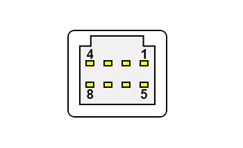
Pin Configuration and Descriptions

Pin Number Description Voltage/Signal Type Maximum Current
1 Power Supply (Vcc) 5V - 24V 5A
2 Ground (GND) - 5A
3 Data+ TTL/CMOS 1A
4 Data- TTL/CMOS 1A
5 Control Signal TTL/CMOS 500mA
6-10 Reserved for Future - -

Note: The above table is an example and the actual pin configuration may vary depending on the specific XCL connector model.

Usage Instructions

How to Use the Component in a Circuit

  1. Power Connections: Connect pin 1 to the positive supply voltage and pin 2 to the ground. Ensure that the supply voltage does not exceed the maximum voltage rating of the connector.
  2. Data Connections: Pins 3 and 4 are used for data transmission. Connect these to your data source and destination, ensuring proper signal integrity.
  3. Control Signal: Pin 5 can be used for additional control signals, such as enabling or disabling the connected device.

Important Considerations and Best Practices

  • Always verify the pinout and electrical specifications of the XCL connector before integrating it into your design.
  • Use proper cable shielding and grounding techniques to minimize electromagnetic interference (EMI).
  • Ensure that the connector is properly seated and locked to prevent accidental disconnections.
  • Avoid exceeding the current and voltage ratings to prevent damage to the connector and connected devices.
  • Regularly inspect connectors for signs of wear or damage, especially in high-vibration environments.

Troubleshooting and FAQs

Common Issues Users Might Face

  • Intermittent Connections: Check for any physical damage to the connector pins or housing. Ensure that the connector is fully engaged and locked.
  • Overheating: If the connector is overheating, it may be due to exceeding the current rating. Reduce the load to within specified limits.
  • Signal Integrity Issues: Use twisted pair cables for data lines and ensure proper termination to avoid reflections and crosstalk.

Solutions and Tips for Troubleshooting

  • Cleaning Contacts: Use a contact cleaner to remove any oxidation or debris from the connector pins.
  • Cable Checks: Inspect cables for any signs of damage or wear. Replace cables if necessary.
  • Secure Mounting: Ensure that the connector is securely mounted to prevent movement that could lead to wear or disconnection.

FAQs

Q: Can the XCL connector be used for power and data simultaneously? A: Yes, the XCL connector is designed to handle both power and data lines, provided the overall specifications are not exceeded.

Q: Is the XCL connector compatible with other standards? A: The XCL connector is designed to comply with the XCL standard and may not be directly compatible with other connector standards. Adapters may be available for interfacing with other systems.

Q: How do I know if my XCL connector is properly seated? A: Most XCL connectors have an audible click or a visual indicator that confirms a secure connection. Always double-check the connector is fully engaged.

Note: This documentation is for informational purposes only. Always consult the manufacturer's datasheet for the most accurate and detailed information about the XCL connector.