How to Use ESP8266 NodeMCU: Examples, Pinouts, and Specs
Introduction
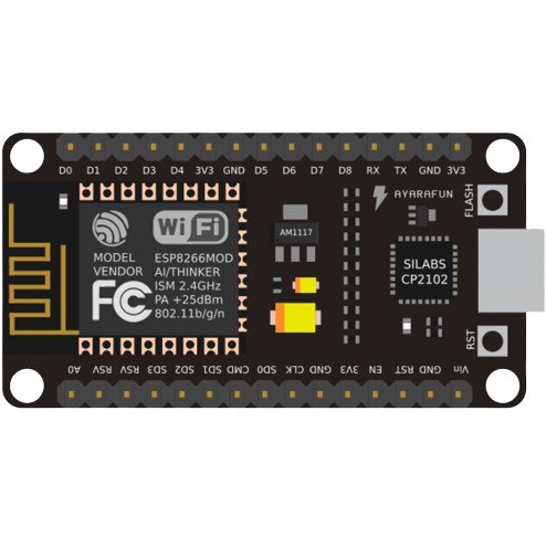
The ESP8266 NodeMCU is a low-cost, open-source IoT platform developed by Espressif Systems. It is based on the ESP8266 / ESP-12E Wi-Fi module and features a built-in microcontroller, enabling seamless integration with various sensors and devices. The NodeMCU is widely used in IoT applications due to its compact size, low power consumption, and ease of programming using the Lua scripting language or the Arduino IDE.
Explore Projects Built with ESP8266 NodeMCU
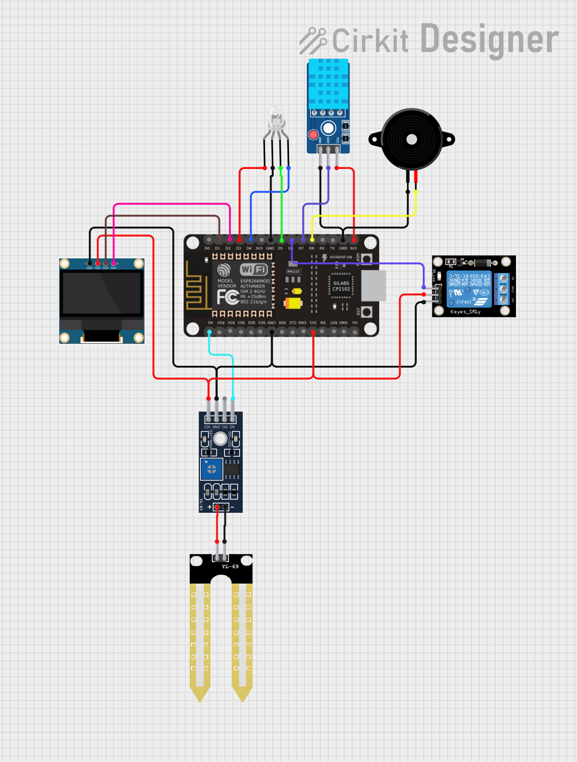
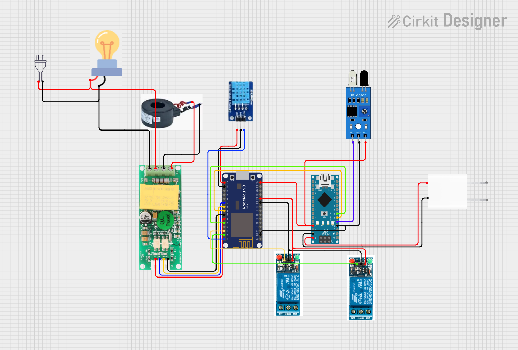
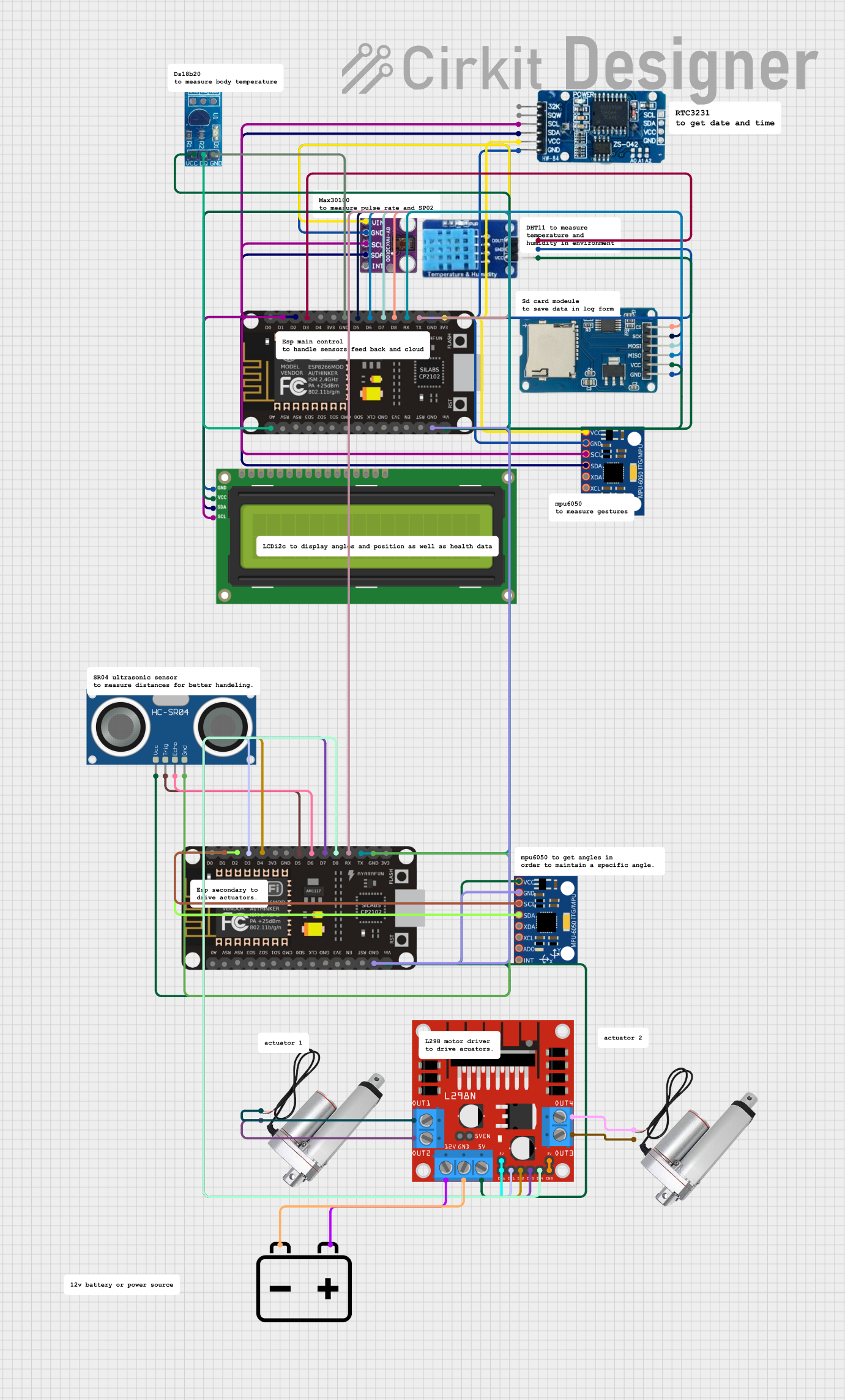
Explore Projects Built with ESP8266 NodeMCU
Common Applications and Use Cases
- Home Automation: Control smart devices such as lights, fans, and appliances.
- IoT Projects: Collect and transmit sensor data to cloud platforms.
- Wireless Communication: Create Wi-Fi-enabled devices for remote monitoring and control.
- Prototyping: Rapid development of connected devices for testing and experimentation.
Technical Specifications
The following table outlines the key technical details of the ESP8266 NodeMCU:
| Parameter | Specification |
|---|---|
| Microcontroller | ESP8266 (Tensilica L106 32-bit RISC processor) |
| Clock Speed | 80 MHz (can be overclocked to 160 MHz) |
| Flash Memory | 4 MB (ESP-12E module) |
| Operating Voltage | 3.3V |
| Input Voltage (VIN) | 4.5V - 10V |
| Digital I/O Pins | 11 (D0-D10) |
| Analog Input Pins | 1 (A0, 10-bit resolution) |
| Wi-Fi Standard | 802.11 b/g/n |
| Power Consumption | 15 µA (deep sleep), 70 mA (active mode) |
| Communication Protocols | UART, SPI, I2C |
| Dimensions | 58 mm x 31 mm |
Pin Configuration and Descriptions
The ESP8266 NodeMCU has a total of 30 pins. Below is a table describing the key pins:
| Pin | Label | Description |
|---|---|---|
| 1 | VIN | Input voltage (4.5V - 10V) |
| 2 | 3V3 | 3.3V output (regulated) |
| 3 | GND | Ground |
| 4 | D0 | GPIO16, can be used as a digital I/O pin |
| 5 | D1 | GPIO5, supports I2C (SCL) |
| 6 | D2 | GPIO4, supports I2C (SDA) |
| 7 | D3 | GPIO0, used for boot mode selection |
| 8 | D4 | GPIO2, onboard LED (active LOW) |
| 9 | D5 | GPIO14, supports SPI (SCLK) |
| 10 | D6 | GPIO12, supports SPI (MISO) |
| 11 | D7 | GPIO13, supports SPI (MOSI) |
| 12 | D8 | GPIO15, supports SPI (CS) |
| 13 | A0 | Analog input (0V - 3.3V, 10-bit resolution) |
| 14 | RST | Reset pin |
Usage Instructions
How to Use the ESP8266 NodeMCU in a Circuit
Powering the Board:
- Connect the VIN pin to a 5V power source (e.g., USB or external power supply).
- Alternatively, use the 3V3 pin for a regulated 3.3V input.
Connecting to Sensors and Actuators:
- Use the digital I/O pins (D0-D10) for controlling devices like LEDs, relays, or motors.
- Use the A0 pin for reading analog sensor values (ensure the input voltage does not exceed 3.3V).
Programming the Board:
- Install the Arduino IDE and add the ESP8266 board package via the Board Manager.
- Connect the NodeMCU to your computer using a micro-USB cable.
- Select the correct board and port in the Arduino IDE, then upload your code.
Important Considerations and Best Practices
- Voltage Levels: Ensure all connected devices operate at 3.3V logic levels to avoid damaging the board.
- Wi-Fi Signal Strength: Place the NodeMCU in an area with a strong Wi-Fi signal for reliable communication.
- Deep Sleep Mode: Use deep sleep mode to conserve power in battery-powered applications.
- Pull-Up/Down Resistors: Use appropriate pull-up or pull-down resistors for GPIO pins to avoid floating states.
Example Code for Arduino IDE
The following example demonstrates how to connect the ESP8266 NodeMCU to a Wi-Fi network and control an onboard LED:
#include <ESP8266WiFi.h> // Include the ESP8266 Wi-Fi library

const char* ssid = "Your_SSID";       // Replace with your Wi-Fi SSID
const char* password = "Your_Password"; // Replace with your Wi-Fi password

void setup() {
  Serial.begin(115200); // Initialize serial communication at 115200 baud
  pinMode(2, OUTPUT);   // Set GPIO2 (D4) as an output pin (onboard LED)

  // Connect to Wi-Fi
  Serial.print("Connecting to Wi-Fi");
  WiFi.begin(ssid, password);
  while (WiFi.status() != WL_CONNECTED) {
    delay(500);
    Serial.print(".");
  }
  Serial.println("\nWi-Fi connected!");
}

void loop() {
  digitalWrite(2, LOW);  // Turn the LED ON (active LOW)
  delay(1000);           // Wait for 1 second
  digitalWrite(2, HIGH); // Turn the LED OFF
  delay(1000);           // Wait for 1 second
}
Troubleshooting and FAQs
Common Issues and Solutions
The board is not detected by the computer:
- Ensure the correct USB driver (e.g., CH340 or CP2102) is installed.
- Try a different USB cable or port.
Wi-Fi connection fails:
- Double-check the SSID and password in your code.
- Ensure the Wi-Fi network is within range and not using unsupported security protocols.
GPIO pins not working as expected:
- Verify that the pins are not in use by other functions (e.g., boot mode).
- Use pull-up or pull-down resistors to stabilize the pin state.
Board resets unexpectedly:
- Check the power supply for stability and ensure it can provide sufficient current.
FAQs
Q: Can the NodeMCU be powered via USB?
A: Yes, the NodeMCU can be powered using a micro-USB cable connected to a 5V USB source.Q: What is the maximum input voltage for the A0 pin?
A: The A0 pin supports a maximum input voltage of 3.3V. Use a voltage divider for higher voltages.Q: Can the NodeMCU operate in standalone mode?
A: Yes, the NodeMCU has a built-in microcontroller and does not require an external MCU.
This concludes the documentation for the ESP8266 NodeMCU.