
How to Use Adafruit INA219 Current Sensor FeatherWing: Examples, Pinouts, and Specs
 Design with Adafruit INA219 Current Sensor FeatherWing in Cirkit Designer
Introduction
The Adafruit INA219 Current Sensor FeatherWing (Manufacturer Part ID: 3650) is a high-precision current sensor designed to measure voltage, current, and power in electronic circuits. It is built specifically for use with Adafruit Feather microcontroller boards, offering seamless integration via the I2C communication protocol. With its ability to measure up to 3.2A of current and a 0.1% accuracy, this sensor is ideal for applications requiring precise power monitoring.
Explore Projects Built with Adafruit INA219 Current Sensor FeatherWing
 Open Project in Cirkit Designer
 Open Project in Cirkit Designer
 Open Project in Cirkit Designer
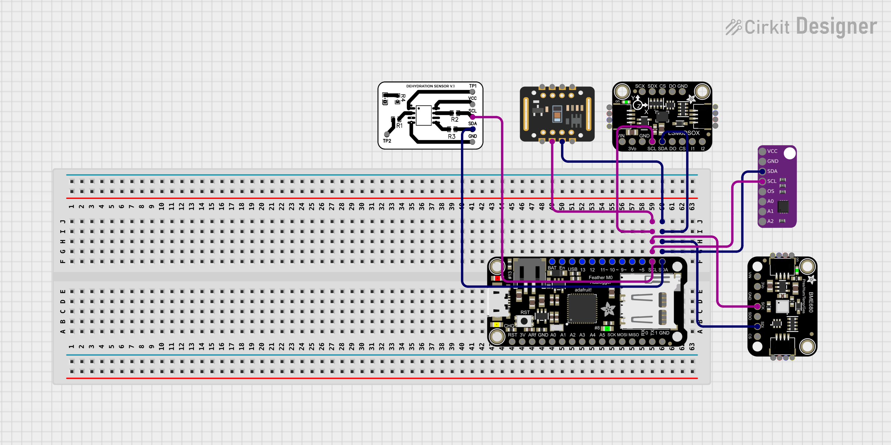 Open Project in Cirkit Designer
Explore Projects Built with Adafruit INA219 Current Sensor FeatherWing
Open Project in Cirkit DesignerOpen Project in Cirkit DesignerOpen Project in Cirkit DesignerOpen Project in Cirkit DesignerCommon Applications and Use Cases
- Battery monitoring in portable devices
- Power consumption analysis in IoT projects
- Solar power system monitoring
- Robotics and motor control systems
- General-purpose current and voltage measurement in electronics projects
Technical Specifications
The following table outlines the key technical details of the Adafruit INA219 Current Sensor FeatherWing:
| Parameter | Value |
|---|---|
| Operating Voltage | 3.3V or 5V (compatible with Feather boards) |
| Current Measurement Range | ±3.2A |
| Voltage Measurement Range | 0V to 26V |
| Accuracy | ±0.1% |
| Communication Protocol | I2C |
| Default I2C Address | 0x40 |
| Dimensions | 50.8mm x 22.8mm x 3.2mm |
| Weight | 4.2g |
Pin Configuration and Descriptions
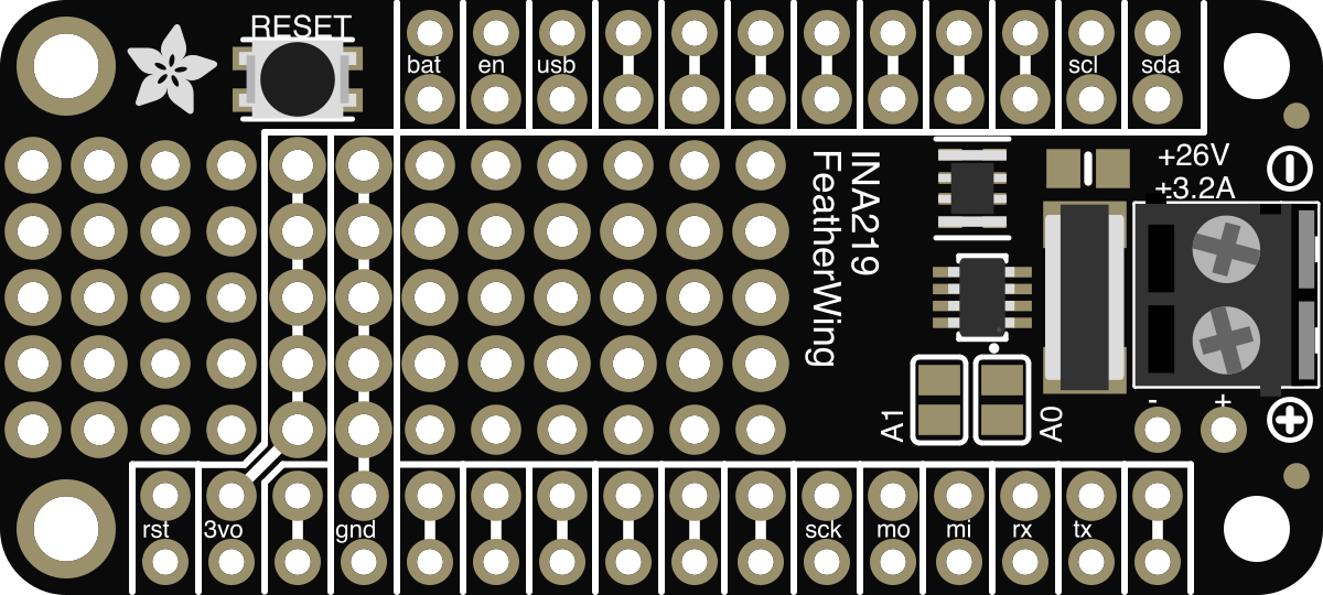
The Adafruit INA219 FeatherWing has the following pin configuration:
| Pin Name | Description |
|---|---|
| VIN+ | Positive input for current measurement (connect to the high side of the load). |
| VIN- | Negative input for current measurement (connect to the low side of the load). |
| SDA | I2C data line (connect to the Feather's SDA pin). |
| SCL | I2C clock line (connect to the Feather's SCL pin). |
| GND | Ground connection. |
| 3V or 5V | Power supply input (connect to the Feather's 3.3V or 5V pin). |
Usage Instructions
How to Use the Component in a Circuit
Wiring the Sensor:
- Connect the VIN+ pin to the positive terminal of the load.
- Connect the VIN- pin to the negative terminal of the load.
- Connect the SDA and SCL pins to the corresponding I2C pins on the Feather board.
- Connect the GND pin to the Feather's ground.
- Connect the 3V or 5V pin to the Feather's power supply pin.
Install the Required Library:
- Download and install the Adafruit INA219 library from the Arduino Library Manager.
- Open the Arduino IDE.
- Go to Sketch > Include Library > Manage Libraries.
- Search for "Adafruit INA219" and click Install.
- Download and install the Adafruit INA219 library from the Arduino Library Manager.
Upload Example Code:
- Use the example code provided below to get started with measuring current, voltage, and power.
Example Code for Arduino UNO
#include <Wire.h>
#include <Adafruit_INA219.h>

// Create an instance of the INA219 sensor
Adafruit_INA219 ina219;

void setup() {
  Serial.begin(115200); // Initialize serial communication at 115200 baud
  while (!Serial) {
    delay(10); // Wait for the Serial Monitor to open
  }

  // Initialize the INA219 sensor
  if (!ina219.begin()) {
    Serial.println("Failed to find INA219 chip");
    while (1) {
      delay(10); // Halt execution if the sensor is not detected
    }
  }
  Serial.println("INA219 sensor initialized successfully!");
}

void loop() {
  // Read current in milliamps
  float current_mA = ina219.getCurrent_mA();
  // Read bus voltage in volts
  float bus_voltage = ina219.getBusVoltage_V();
  // Read power in milliwatts
  float power_mW = ina219.getPower_mW();

  // Print the measurements to the Serial Monitor
  Serial.print("Current (mA): ");
  Serial.println(current_mA);
  Serial.print("Bus Voltage (V): ");
  Serial.println(bus_voltage);
  Serial.print("Power (mW): ");
  Serial.println(power_mW);
  Serial.println();

  delay(1000); // Wait 1 second before taking the next reading
}
Important Considerations and Best Practices
- Ensure that the current flowing through the sensor does not exceed the ±3.2A limit to avoid damage.
- Use appropriately rated wires and connectors for the current being measured.
- If multiple INA219 sensors are used on the same I2C bus, configure unique I2C addresses for each sensor by adjusting the address jumpers on the FeatherWing.
- Avoid placing the sensor near high-frequency noise sources to maintain measurement accuracy.
Troubleshooting and FAQs
Common Issues and Solutions
Sensor Not Detected:
- Ensure the I2C connections (SDA and SCL) are properly wired to the Feather board.
- Verify that the correct I2C address (default: 0x40) is being used in the code.
- Check the power supply voltage (3.3V or 5V) to ensure the sensor is powered correctly.
Incorrect Current or Voltage Readings:
- Verify that the load connections to VIN+ and VIN- are secure and correct.
- Ensure the current being measured is within the ±3.2A range.
- Check for loose or damaged wires in the circuit.
No Output on Serial Monitor:
- Confirm that the Serial Monitor baud rate matches the
Serial.begin()value in the code. - Ensure the Feather board is properly connected to the computer via USB.
- Confirm that the Serial Monitor baud rate matches the
FAQs
Q: Can the INA219 FeatherWing measure negative currents?
A: Yes, the INA219 can measure bidirectional currents, allowing it to detect both positive and negative current flow.
Q: How do I change the I2C address of the INA219?
A: The I2C address can be changed by soldering the address jumpers on the back of the FeatherWing. Refer to the Adafruit guide for detailed instructions.
Q: Can I use this sensor with non-Feather boards?
A: Yes, the INA219 FeatherWing can be used with other microcontrollers that support I2C communication, such as Arduino UNO or ESP32. Ensure proper wiring and voltage compatibility.
Q: What is the maximum voltage the sensor can measure?
A: The INA219 can measure up to 26V on the bus voltage input.
By following this documentation, you can effectively integrate the Adafruit INA219 Current Sensor FeatherWing into your projects for accurate current, voltage, and power measurements.