How to Use Connector 2 In 4 Out: Examples, Pinouts, and Specs
Introduction
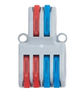
The Connector 2 In 4 Out is a versatile electronic component designed to distribute two input signals to four output channels. It is commonly used in audio and video applications for signal routing, enabling efficient signal distribution without the need for complex circuitry. This component is ideal for scenarios where multiple devices need to receive the same input signal, such as in home theater systems, professional audio setups, or video broadcasting.
Explore Projects Built with Connector 2 In 4 Out


Explore Projects Built with Connector 2 In 4 Out
Common Applications
- Audio signal distribution to multiple speakers or amplifiers
- Video signal routing to multiple displays or monitors
- Signal duplication in testing and prototyping environments
- Home theater and multimedia systems
Technical Specifications
The Connector 2 In 4 Out is a passive component, meaning it does not require an external power source to operate. Below are its key technical details:
| Parameter | Specification |
|---|---|
| Input Channels | 2 |
| Output Channels | 4 |
| Signal Type | Analog or Digital (Audio/Video) |
| Frequency Range | 20 Hz to 20 kHz (Audio) |
| Impedance | 75 Ω (Video), 10 kΩ (Audio) |
| Connector Type | RCA, 3.5mm, or custom (varies by model) |
| Maximum Signal Voltage | 5V peak-to-peak |
| Dimensions | Varies by model (e.g., 50mm x 30mm) |
Pin Configuration and Descriptions
The pin configuration for the Connector 2 In 4 Out depends on the specific model. Below is a general description for a typical RCA-based version:
| Pin | Label | Description |
|---|---|---|
| 1 | Input 1 (L) | Left channel input signal |
| 2 | Input 2 (R) | Right channel input signal |
| 3 | Output 1 (L) | Left channel output signal 1 |
| 4 | Output 2 (L) | Left channel output signal 2 |
| 5 | Output 3 (R) | Right channel output signal 1 |
| 6 | Output 4 (R) | Right channel output signal 2 |
| 7 | Ground (GND) | Common ground for all signals |
Usage Instructions
How to Use the Component in a Circuit
- Connect the Inputs: Attach the input signals to the designated input pins (e.g., Input 1 and Input 2). Ensure the signal type (audio or video) matches the component's specifications.
- Connect the Outputs: Attach the output devices (e.g., speakers, displays) to the corresponding output pins.
- Ground Connection: Connect the ground pin (GND) to the common ground of your circuit to ensure proper signal integrity.
- Verify Signal Compatibility: Ensure the input and output devices are compatible with the component's impedance and voltage ratings.
Important Considerations and Best Practices
- Signal Loss: As a passive component, the Connector 2 In 4 Out may introduce slight signal attenuation. Use amplifiers if necessary to maintain signal strength.
- Cable Quality: Use high-quality cables to minimize noise and signal degradation, especially for long cable runs.
- Impedance Matching: Ensure proper impedance matching between the input source, connector, and output devices to avoid signal reflections or distortion.
- Avoid Overloading: Do not exceed the maximum signal voltage (5V peak-to-peak) to prevent damage to the component or connected devices.
Example: Using with an Arduino UNO
While the Connector 2 In 4 Out is not directly programmable, it can be used in conjunction with an Arduino UNO to route signals. For example, you can use the Arduino to generate an audio signal and route it through the connector.
/*
  Example: Generating a simple audio signal with Arduino
  This code generates a square wave on pin 9, which can be routed
  through the Connector 2 In 4 Out to multiple output devices.
*/

const int audioPin = 9; // Pin connected to the input of the connector

void setup() {
  pinMode(audioPin, OUTPUT); // Set the pin as an output
}

void loop() {
  digitalWrite(audioPin, HIGH); // Generate a high signal
  delay(1); // Delay for 1ms (adjust for desired frequency)
  digitalWrite(audioPin, LOW); // Generate a low signal
  delay(1); // Delay for 1ms
}
Troubleshooting and FAQs
Common Issues and Solutions
No Signal at Outputs
- Cause: Loose or incorrect connections.
- Solution: Verify all input and output connections. Ensure the ground pin is properly connected.
Signal Distortion
- Cause: Impedance mismatch or poor cable quality.
- Solution: Use impedance-matched devices and high-quality cables.
Signal Attenuation
- Cause: Passive nature of the component.
- Solution: Use an amplifier to boost the signal strength if necessary.
Interference or Noise
- Cause: Electromagnetic interference or ground loops.
- Solution: Use shielded cables and ensure a proper ground connection.
FAQs
Q: Can this component handle digital signals?
A: Yes, the Connector 2 In 4 Out can handle both analog and digital signals, provided the signal voltage does not exceed 5V peak-to-peak.
Q: Is this component suitable for HDMI or high-definition video signals?
A: No, this component is designed for low-frequency analog or digital signals. For HDMI or high-definition video, use a dedicated HDMI splitter.
Q: Can I use this component with a microcontroller?
A: Yes, you can use it to route signals generated by a microcontroller, such as audio signals from an Arduino.
Q: Does this component require external power?
A: No, it is a passive component and does not require an external power source.