How to Use ESP32: Examples, Pinouts, and Specs
Introduction
The ESP32 is a low-cost, low-power system on a chip (SoC) developed by Arduino (Manufacturer Part ID: UNO). It features integrated Wi-Fi and Bluetooth capabilities, making it an ideal choice for Internet of Things (IoT) applications, smart devices, and embedded systems. The ESP32 is highly versatile, offering dual-core processing, a wide range of GPIO pins, and support for various communication protocols.
Explore Projects Built with ESP32


Explore Projects Built with ESP32
Common Applications and Use Cases
- IoT devices (e.g., smart home automation, environmental monitoring)
- Wireless communication systems
- Wearable devices
- Robotics and automation
- Data logging and remote sensing
- Prototyping and educational projects
Technical Specifications
The ESP32 is a powerful and feature-rich microcontroller. Below are its key technical specifications:
| Parameter | Value |
|---|---|
| Manufacturer | Arduino |
| Part ID | UNO |
| Processor | Dual-core Xtensa® 32-bit LX6 microprocessor |
| Clock Speed | Up to 240 MHz |
| Flash Memory | 4 MB (varies by model) |
| SRAM | 520 KB |
| Wi-Fi | 802.11 b/g/n |
| Bluetooth | Bluetooth 4.2 and BLE (Bluetooth Low Energy) |
| Operating Voltage | 3.3V |
| Input Voltage Range | 3.0V to 3.6V |
| GPIO Pins | 34 (multipurpose, including ADC, DAC, PWM, I2C, SPI, UART, etc.) |
| ADC Channels | 18 (12-bit resolution) |
| DAC Channels | 2 |
| Communication Protocols | UART, SPI, I2C, I2S, CAN, Ethernet, PWM |
| Power Consumption | Ultra-low power consumption with multiple power modes |
| Operating Temperature | -40°C to +125°C |
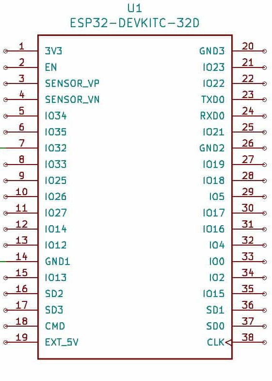
Pin Configuration and Descriptions
The ESP32 has a rich set of GPIO pins, which can be configured for various functions. Below is a table summarizing the key pins:
| Pin Name | Function | Description |
|---|---|---|
| GPIO0 | Input/Output, Boot Mode Select | Used for boot mode selection during startup. |
| GPIO1 (TXD0) | UART TX | Default UART transmit pin. |
| GPIO3 (RXD0) | UART RX | Default UART receive pin. |
| GPIO12-15 | Input/Output, ADC, PWM, etc. | Multipurpose pins for analog/digital input/output, PWM, and other functions. |
| GPIO34-39 | Input Only | Analog input pins (ADC) with no digital output capability. |
| EN | Enable | Chip enable pin. Pulling low disables the chip. |
| 3V3 | Power Supply | 3.3V power supply input/output. |
| GND | Ground | Ground connection. |
Usage Instructions
The ESP32 can be used in a wide range of applications. Below are the steps to use it in a circuit and some best practices:
Connecting the ESP32 to an Arduino UNO
- Power Supply: Ensure the ESP32 is powered with 3.3V. Do not connect it directly to 5V as it may damage the chip.
- Communication: Use UART (TX/RX) pins to communicate between the Arduino UNO and the ESP32.
- GPIO Usage: Configure the GPIO pins as needed for your application (e.g., input, output, ADC, PWM).
- Programming: Use the Arduino IDE to program the ESP32. Install the ESP32 board package in the Arduino IDE via the Board Manager.
Sample Code for Wi-Fi Connection
Below is an example of how to connect the ESP32 to a Wi-Fi network using the Arduino IDE:
#include <WiFi.h> // Include the Wi-Fi library for ESP32

// Replace with your network credentials
const char* ssid = "Your_SSID";
const char* password = "Your_PASSWORD";

void setup() {
  Serial.begin(115200); // Initialize serial communication at 115200 baud
  delay(1000); // Wait for a second to stabilize

  Serial.println("Connecting to Wi-Fi...");
  WiFi.begin(ssid, password); // Start Wi-Fi connection

  // Wait until the ESP32 connects to the Wi-Fi network
  while (WiFi.status() != WL_CONNECTED) {
    delay(500);
    Serial.print(".");
  }

  Serial.println("\nWi-Fi connected!");
  Serial.print("IP Address: ");
  Serial.println(WiFi.localIP()); // Print the assigned IP address
}

void loop() {
  // Add your main code here
}
Best Practices
- Use a level shifter if interfacing the ESP32 with 5V logic devices.
- Avoid using GPIO pins 6-11 as they are connected to the internal flash memory.
- Use decoupling capacitors near the power pins to ensure stable operation.
- When using Wi-Fi or Bluetooth, ensure proper antenna placement for optimal signal strength.
Troubleshooting and FAQs
Common Issues
ESP32 Not Connecting to Wi-Fi
- Ensure the SSID and password are correct.
- Check if the Wi-Fi network is within range.
- Verify that the ESP32 is powered correctly (3.3V).
Serial Monitor Not Displaying Output
- Ensure the correct COM port is selected in the Arduino IDE.
- Check the baud rate in the Serial Monitor matches the
Serial.begin()value.
GPIO Pins Not Working
- Verify the pin mode is set correctly in the code (e.g.,
pinMode(pin, OUTPUT)). - Avoid using reserved pins (e.g., GPIO6-11).
- Verify the pin mode is set correctly in the code (e.g.,
Tips for Troubleshooting
- Use a multimeter to check power supply voltage and continuity.
- Test the ESP32 with a simple "blink" program to ensure it is functioning.
- Update the ESP32 board package in the Arduino IDE to the latest version.
By following this documentation, you can effectively use the ESP32 in your projects and troubleshoot common issues.