How to Use AKK AT18 FPV Transmitter Race Ranger: Examples, Pinouts, and Specs
AKK AT18 FPV Transmitter Race Ranger Documentation
1. Introduction
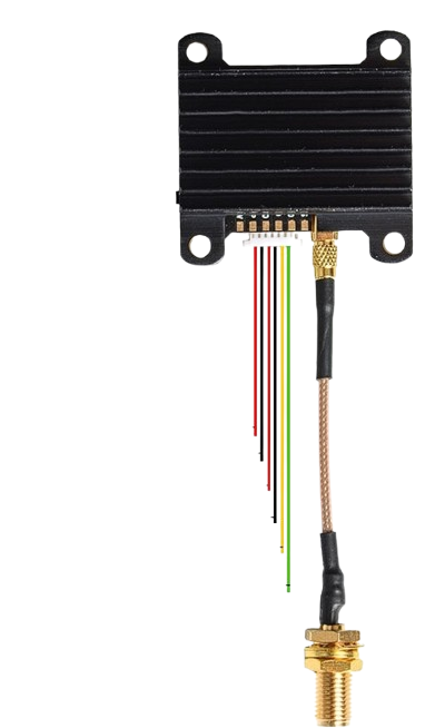
The AKK AT18 FPV Transmitter Race Ranger is a high-performance video transmitter designed specifically for FPV (First Person View) racing drones. Its compact and lightweight design makes it an excellent choice for drone pilots who prioritize speed, agility, and reliability. The transmitter supports adjustable power output, multiple frequency channels, and a durable build to endure the demanding conditions of FPV racing.
Key Features:
- Adjustable power output: 25mW, 200mW, 500mW, and 800mW.
- 48 frequency channels, including RaceBand.
- Compact and lightweight design for easy integration.
- Robust construction to withstand crashes and vibrations.
- Low latency for real-time video transmission.
- Smart audio support for remote control of settings via compatible flight controllers.
Common Applications:
- FPV racing drones.
- Freestyle FPV drones.
- Long-range FPV setups.
- Aerial photography and videography drones requiring real-time video feedback.
2. Technical Specifications
The following table outlines the key technical details of the AKK AT18 FPV Transmitter Race Ranger:
| Parameter | Specification |
|---|---|
| Input Voltage | 7V - 24V (2S to 6S LiPo) |
| Power Output | 25mW / 200mW / 500mW / 800mW |
| Frequency Channels | 48 channels (including RaceBand) |
| Frequency Range | 5.8GHz (5.645GHz - 5.945GHz) |
| Video Format | NTSC / PAL |
| Antenna Connector | MMCX |
| Dimensions | 36mm x 36mm x 5mm |
| Weight | 8g (without antenna) |
| Operating Temperature | -10°C to 60°C |
Pin Configuration and Descriptions
The AKK AT18 FPV Transmitter has the following pinout:
| Pin | Label | Description |
|---|---|---|
| 1 | VIN | Power input (7V - 24V). Connect to the drone's power distribution board (PDB). |
| 2 | GND | Ground connection. |
| 3 | VIDEO IN | Video signal input from the camera. |
| 4 | AUDIO IN | Audio signal input (optional). |
| 5 | TX | Smart audio control signal (connect to flight controller UART TX). |
3. Usage Instructions
Connecting the AKK AT18 to Your Drone
- Power Connection: Connect the VIN pin to a 7V-24V power source (e.g., the drone's PDB or battery). Connect the GND pin to the ground.
- Video Input: Connect the VIDEO IN pin to the video output of your FPV camera.
- Audio Input (Optional): If your FPV camera supports audio, connect the AUDIO IN pin to the camera's audio output.
- Smart Audio: Connect the TX pin to a UART TX pin on your flight controller for remote control of the transmitter's settings.
- Antenna: Attach a 5.8GHz antenna to the MMCX connector. Ensure the antenna is securely connected before powering on the transmitter to avoid damage.
Configuring the Transmitter
- Use the onboard button to change frequency channels, bands, and power output. Refer to the included frequency chart for channel selection.
- If using Smart Audio, configure the transmitter settings via your flight controller's OSD (On-Screen Display) or Betaflight Configurator.
Best Practices
- Always ensure the antenna is connected before powering on the transmitter to prevent damage.
- Avoid operating the transmitter at high power levels (e.g., 800mW) for extended periods without proper cooling.
- Use a low-power setting (e.g., 25mW) for bench testing to minimize interference with other devices.
4. Example Code for Smart Audio Configuration with Arduino UNO
The AKK AT18 supports Smart Audio, which allows you to control its settings via a UART interface. Below is an example of how to send a command to the transmitter using an Arduino UNO:
#include <SoftwareSerial.h>

// Define the TX pin for Smart Audio communication
#define SMART_AUDIO_TX 10

// Initialize SoftwareSerial for Smart Audio
SoftwareSerial smartAudio(255, SMART_AUDIO_TX); // RX pin is not used

void setup() {
  // Start the serial communication for Smart Audio
  smartAudio.begin(9600); // Smart Audio typically uses 9600 baud rate

  // Send a command to set the transmitter to 25mW power output
  sendSmartAudioCommand(0x01, 0x01); // Example command: Band 1, Channel 1
}

void loop() {
  // No continuous actions required in this example
}

// Function to send a Smart Audio command
void sendSmartAudioCommand(uint8_t band, uint8_t channel) {
  uint8_t command[3];
  command[0] = 0xAA; // Start byte for Smart Audio
  command[1] = (band << 4) | channel; // Combine band and channel into one byte
  command[2] = command[0] ^ command[1]; // Checksum (XOR of previous bytes)

  // Send the command over Smart Audio
  for (int i = 0; i < 3; i++) {
    smartAudio.write(command[i]);
  }
}
Notes:
- Replace
0x01and0x01in thesendSmartAudioCommandfunction with the desired band and channel values. - Ensure the Arduino UNO's TX pin is connected to the AKK AT18's TX pin.
5. Troubleshooting and FAQs
Common Issues and Solutions
| Issue | Possible Cause | Solution |
|---|---|---|
| No video signal on the FPV goggles. | Incorrect wiring or channel mismatch. | Verify all connections and ensure the transmitter and goggles are on the same channel. |
| Transmitter overheating. | Prolonged use at high power output. | Use a lower power setting or improve airflow around the transmitter. |
| Poor video quality or interference. | Antenna issue or nearby interference. | Check the antenna connection and ensure no other devices are using the same frequency. |
| Smart Audio not working. | Incorrect UART configuration. | Verify the flight controller's UART settings and wiring. |
FAQs
Q1: Can I use the AKK AT18 with a 3S LiPo battery?
A1: Yes, the transmitter supports input voltages from 7V to 24V, so a 3S LiPo (11.1V) is compatible.
Q2: How do I change the power output?
A2: You can change the power output using the onboard button or via Smart Audio if connected to a flight controller.
Q3: What is the range of the AKK AT18?
A3: The range depends on the power output, antenna type, and environmental conditions. At 800mW, it can achieve several kilometers in open areas.
This documentation provides a comprehensive guide to using the AKK AT18 FPV Transmitter Race Ranger. For further assistance, refer to the manufacturer's user manual or contact their support team.
Explore Projects Built with AKK AT18 FPV Transmitter Race Ranger
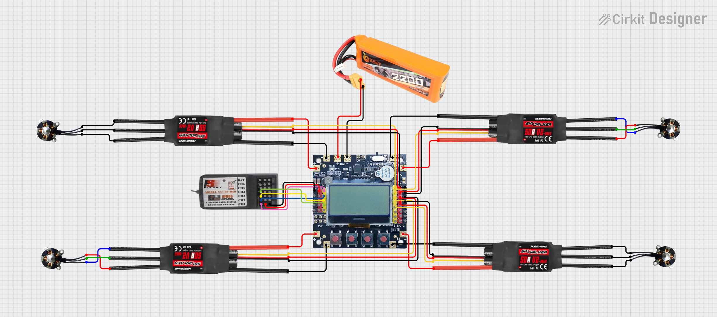

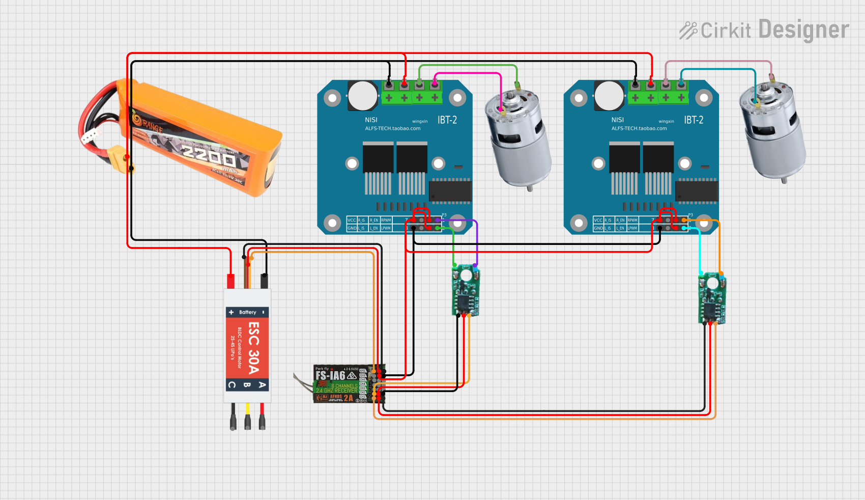

Explore Projects Built with AKK AT18 FPV Transmitter Race Ranger