How to Use Pwm Fan: Examples, Pinouts, and Specs

Introduction
A PWM (Pulse Width Modulation) fan is a type of cooling fan that uses PWM signals to control its speed. By varying the duty cycle of the signal, the fan can operate at different speeds, allowing for efficient cooling and reduced noise levels. PWM fans are widely used in applications where precise temperature control and energy efficiency are critical.
Explore Projects Built with Pwm Fan
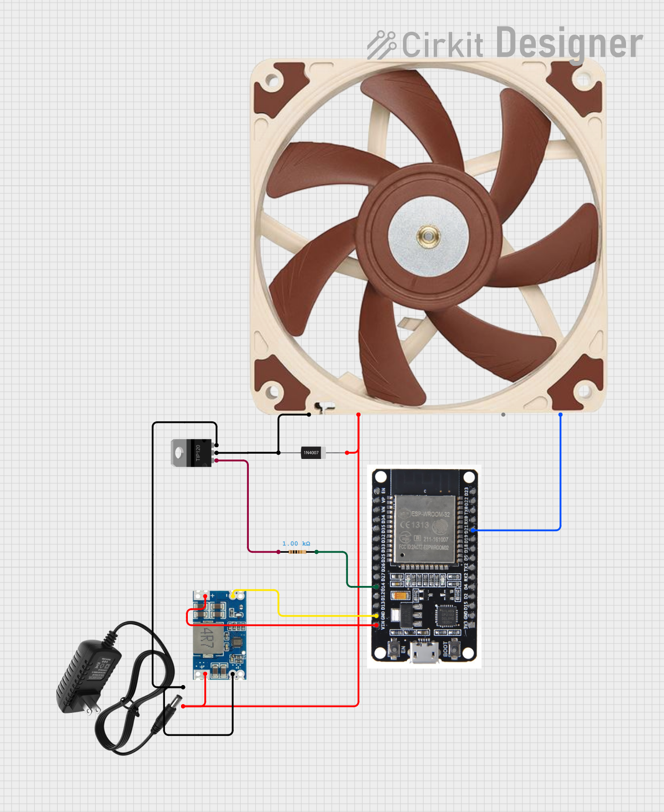

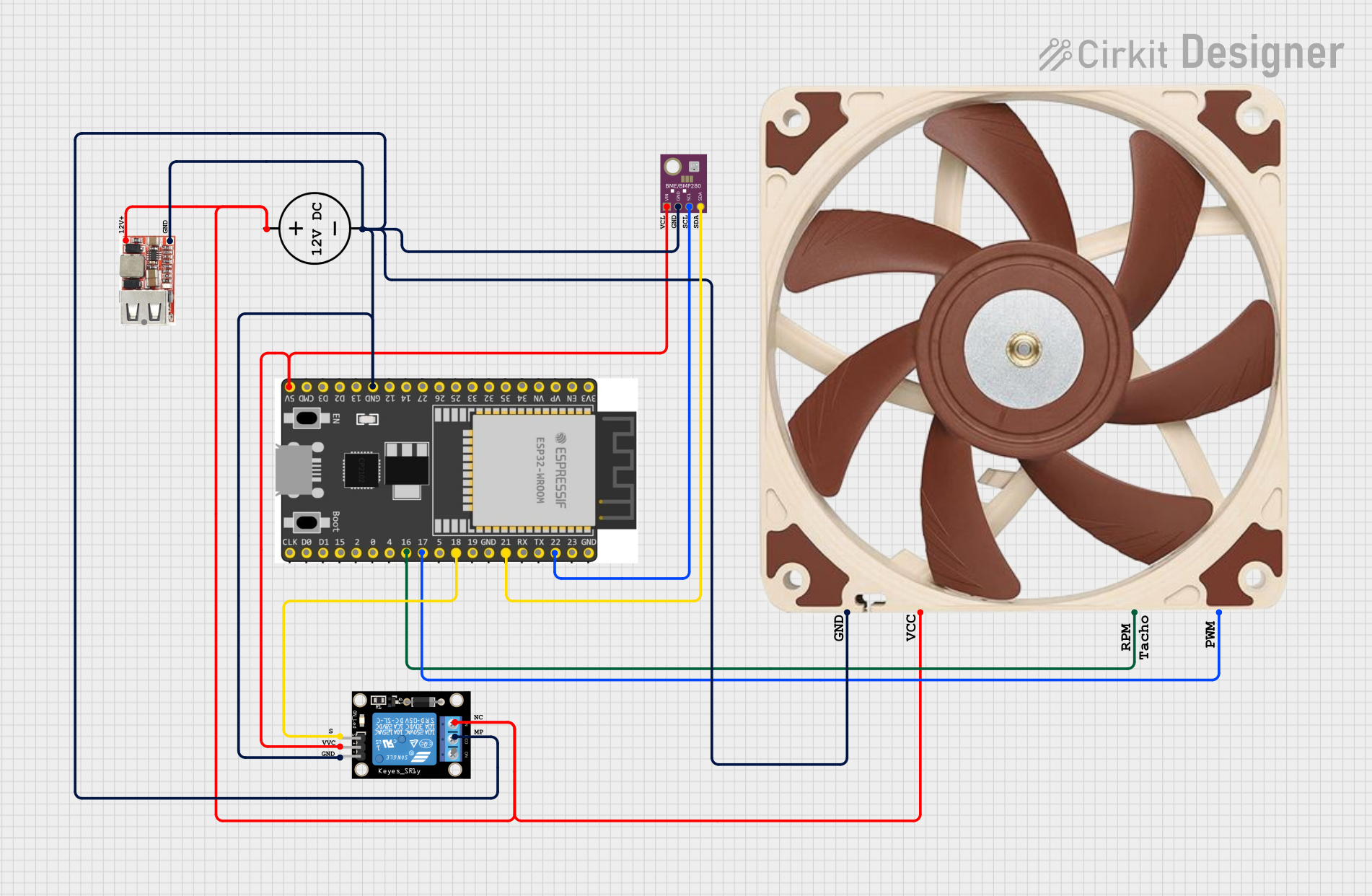
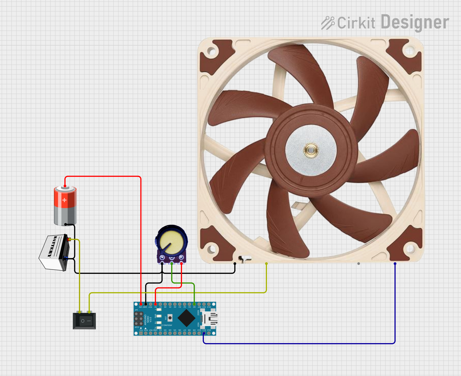
Explore Projects Built with Pwm Fan
Common Applications and Use Cases
- Computer cooling systems (e.g., CPU, GPU, and case fans)
- Industrial equipment requiring temperature regulation
- Home appliances such as air purifiers and HVAC systems
- Embedded systems and microcontroller-based projects
- Noise-sensitive environments where fan speed control is essential
Technical Specifications
Key Technical Details
- Operating Voltage: Typically 12V DC (varies by model, check datasheet)
- Current Rating: 0.1A to 1A (depending on fan size and model)
- PWM Signal Voltage: 3.3V or 5V logic level (TTL compatible)
- PWM Frequency: 20 kHz (standard for most PWM fans)
- Speed Control Range: 0% to 100% duty cycle
- Connector Type: 4-pin Molex (standard for PWM fans)
Pin Configuration and Descriptions
The PWM fan typically uses a 4-pin connector. The pinout is as follows:
| Pin Number | Name | Description |
|---|---|---|
| 1 | GND | Ground connection for the fan |
| 2 | VCC | Power supply for the fan (typically 12V DC) |
| 3 | Tachometer | Output signal for fan speed monitoring (provides pulses proportional to RPM) |
| 4 | PWM | Input signal for speed control (3.3V or 5V PWM signal) |
Usage Instructions
How to Use the Component in a Circuit
- Power Connection: Connect the VCC pin to a 12V DC power source and the GND pin to the ground.
- PWM Signal: Use a microcontroller (e.g., Arduino) or a dedicated PWM controller to generate a PWM signal. Connect this signal to the PWM pin of the fan.
- Tachometer Monitoring: If you need to monitor the fan's speed, connect the Tachometer pin to a microcontroller's input pin and measure the frequency of the pulses.
Important Considerations and Best Practices
- Ensure the power supply matches the fan's voltage and current requirements.
- Use a pull-up resistor (typically 10kΩ) on the Tachometer pin if the microcontroller requires it.
- Avoid setting the PWM duty cycle to 0% for extended periods, as some fans may stop completely and fail to restart.
- Use a PWM frequency of 20 kHz to minimize audible noise from the fan.
- Verify the fan's datasheet for specific requirements, as some models may have unique characteristics.
Example: Connecting a PWM Fan to an Arduino UNO
Below is an example of how to control a PWM fan using an Arduino UNO:
// Define the PWM pin connected to the fan
const int pwmPin = 9; // Pin 9 supports PWM on Arduino UNO

void setup() {
  // Set the PWM pin as an output
  pinMode(pwmPin, OUTPUT);
}

void loop() {
  // Gradually increase fan speed from 0% to 100%
  for (int dutyCycle = 0; dutyCycle <= 255; dutyCycle++) {
    analogWrite(pwmPin, dutyCycle); // Set PWM duty cycle
    delay(20); // Wait 20ms before increasing duty cycle
  }

  // Gradually decrease fan speed from 100% to 0%
  for (int dutyCycle = 255; dutyCycle >= 0; dutyCycle--) {
    analogWrite(pwmPin, dutyCycle); // Set PWM duty cycle
    delay(20); // Wait 20ms before decreasing duty cycle
  }
}
Note: The analogWrite() function generates a PWM signal with a frequency of approximately 490 Hz on most Arduino pins. While this is sufficient for basic control, some fans may require a higher frequency (e.g., 20 kHz). In such cases, you may need to use a library or configure the Arduino's timers manually.
Troubleshooting and FAQs
Common Issues and Solutions
Fan Not Spinning:
- Cause: Insufficient power supply or incorrect wiring.
- Solution: Verify the power supply voltage and current. Check all connections.
Fan Speed Not Changing:
- Cause: Incorrect PWM signal or frequency.
- Solution: Ensure the PWM signal is within the fan's specifications (e.g., 3.3V or 5V logic level, 20 kHz frequency).
Fan Produces Audible Noise:
- Cause: Low PWM frequency.
- Solution: Increase the PWM frequency to 20 kHz or higher.
Tachometer Signal Not Detected:
- Cause: Missing pull-up resistor or incorrect connection.
- Solution: Add a pull-up resistor to the Tachometer pin and verify the wiring.
FAQs
Can I use a 3-pin fan with PWM control? No, 3-pin fans do not have a dedicated PWM pin. Speed control is achieved by varying the supply voltage, which is less precise.
What happens if I set the PWM duty cycle to 0%? Most fans will stop spinning. However, some fans may require a minimum duty cycle (e.g., 20%) to start spinning again.
Can I use a 5V power supply for a 12V PWM fan? No, the fan will not operate correctly. Always use the specified voltage for the fan.
How do I measure the fan's RPM using the Tachometer pin? Count the number of pulses from the Tachometer pin in one second. Multiply this value by 30 to calculate the RPM (most fans produce 2 pulses per revolution).