
How to Use Adafruit LSM6DS33 6-DoF Accel + Gyro IMU: Examples, Pinouts, and Specs
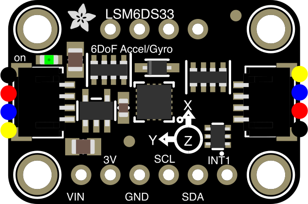
 Design with Adafruit LSM6DS33 6-DoF Accel + Gyro IMU in Cirkit Designer
Introduction
The Adafruit LSM6DS33 (Part ID: 4480) is a compact and versatile inertial measurement unit (IMU) that integrates a 3-axis accelerometer and a 3-axis gyroscope. This sensor is designed to measure linear acceleration and angular velocity, making it ideal for motion sensing and orientation tracking. Its small form factor and high precision make it suitable for a wide range of applications, including robotics, drones, wearable devices, and gaming peripherals.
Explore Projects Built with Adafruit LSM6DS33 6-DoF Accel + Gyro IMU
 Open Project in Cirkit Designer
 Open Project in Cirkit Designer
 Open Project in Cirkit Designer
 Open Project in Cirkit Designer
Explore Projects Built with Adafruit LSM6DS33 6-DoF Accel + Gyro IMU
Open Project in Cirkit DesignerOpen Project in Cirkit DesignerOpen Project in Cirkit DesignerOpen Project in Cirkit DesignerCommon Applications
- Robotics for motion tracking and navigation
- Drones for stabilization and orientation control
- Wearable devices for activity monitoring
- Gaming peripherals for motion-based input
- Industrial equipment for vibration analysis
Technical Specifications
The Adafruit LSM6DS33 is built on STMicroelectronics' LSM6DS33 chip and offers the following key specifications:
| Parameter | Value |
|---|---|
| Operating Voltage | 3.3V (logic level) |
| Communication Interface | I2C (default address: 0x6A or 0x6B) and SPI |
| Accelerometer Range | ±2g, ±4g, ±8g, ±16g (configurable) |
| Gyroscope Range | ±125°/s, ±250°/s, ±500°/s, ±1000°/s, ±2000°/s (configurable) |
| Output Data Rate (ODR) | Up to 6.66 kHz for both accelerometer and gyroscope |
| Operating Temperature Range | -40°C to +85°C |
| Dimensions | 20mm x 18mm x 2mm |
Pin Configuration and Descriptions
The LSM6DS33 breakout board has the following pin layout:
| Pin Name | Description |
|---|---|
| VIN | Power input (3.3V or 5V) |
| GND | Ground connection |
| SCL | I2C clock line (or SPI clock line in SPI mode) |
| SDA | I2C data line (or SPI MOSI line in SPI mode) |
| CS | Chip select for SPI communication (active low) |
| INT1 | Interrupt 1 output (can be configured for various events) |
| INT2 | Interrupt 2 output (can be configured for various events) |
Usage Instructions
How to Use the LSM6DS33 in a Circuit
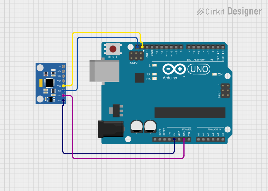
- Power the Sensor: Connect the VIN pin to a 3.3V or 5V power source and the GND pin to ground.
- Choose Communication Protocol:
- For I2C: Connect the SCL and SDA pins to the corresponding I2C pins on your microcontroller.
- For SPI: Connect the SCL, SDA, and CS pins to the SPI clock, MOSI, and chip select pins, respectively.
- Configure the Sensor: Use the Adafruit LSM6DS33 library to initialize and configure the sensor for your application.
- Read Data: Use the library functions to read accelerometer and gyroscope data.
Important Considerations
- Pull-Up Resistors: The I2C lines (SCL and SDA) require pull-up resistors. The breakout board includes 10kΩ pull-ups by default.
- Voltage Compatibility: Ensure your microcontroller's logic level matches the sensor's 3.3V logic level.
- Interrupts: Configure the INT1 and INT2 pins for specific events, such as data ready or motion detection.
Example Code for Arduino UNO
Below is an example of how to use the LSM6DS33 with an Arduino UNO via I2C:
#include <Wire.h>
#include <Adafruit_LSM6DS33.h>

// Create an instance of the LSM6DS33 class
Adafruit_LSM6DS33 lsm6ds33;

void setup() {
  Serial.begin(115200);
  while (!Serial) {
    delay(10); // Wait for Serial Monitor to open
  }

  // Initialize the LSM6DS33 sensor
  if (!lsm6ds33.begin_I2C()) {
    Serial.println("Failed to find LSM6DS33 chip");
    while (1) {
      delay(10); // Halt if sensor initialization fails
    }
  }
  Serial.println("LSM6DS33 Found!");

  // Configure the accelerometer and gyroscope ranges
  lsm6ds33.setAccelRange(LSM6DS_ACCEL_RANGE_4_G);
  lsm6ds33.setGyroRange(LSM6DS_GYRO_RANGE_250_DPS);

  // Set the output data rate
  lsm6ds33.setAccelDataRate(LSM6DS_RATE_104_HZ);
  lsm6ds33.setGyroDataRate(LSM6DS_RATE_104_HZ);
}

void loop() {
  sensors_event_t accel, gyro, temp;

  // Get sensor events
  lsm6ds33.getEvent(&accel, &gyro, &temp);

  // Print accelerometer data
  Serial.print("Accel X: "); Serial.print(accel.acceleration.x); Serial.print(" m/s^2 ");
  Serial.print("Y: "); Serial.print(accel.acceleration.y); Serial.print(" m/s^2 ");
  Serial.print("Z: "); Serial.print(accel.acceleration.z); Serial.println(" m/s^2");

  // Print gyroscope data
  Serial.print("Gyro X: "); Serial.print(gyro.gyro.x); Serial.print(" rad/s ");
  Serial.print("Y: "); Serial.print(gyro.gyro.y); Serial.print(" rad/s ");
  Serial.print("Z: "); Serial.print(gyro.gyro.z); Serial.println(" rad/s");

  // Print temperature data
  Serial.print("Temperature: "); Serial.print(temp.temperature); Serial.println(" °C");

  delay(500); // Delay for readability
}
Troubleshooting and FAQs
Common Issues
Sensor Not Detected:
- Ensure the I2C address (0x6A or 0x6B) matches the configuration in your code.
- Check the wiring for loose or incorrect connections.
- Verify that the sensor is powered correctly.
Incorrect or No Data:
- Confirm that the accelerometer and gyroscope ranges are set appropriately for your application.
- Ensure the output data rate is not too high for your microcontroller to handle.
Interrupts Not Working:
- Verify that the INT1 and INT2 pins are connected to the correct microcontroller pins.
- Check the interrupt configuration in your code.
Tips for Troubleshooting
- Use a logic analyzer or oscilloscope to verify I2C or SPI communication.
- Test the sensor with the Adafruit example sketches to rule out hardware issues.
- Double-check the power supply voltage and logic level compatibility.
FAQs
Q: Can I use the LSM6DS33 with a 5V microcontroller?
A: Yes, the breakout board includes a voltage regulator and level shifters, making it compatible with 5V systems.
Q: How do I change the I2C address?
A: The I2C address can be changed by connecting the SDO pin to GND (0x6A) or VIN (0x6B).
Q: What is the maximum cable length for I2C communication?
A: The maximum length depends on the pull-up resistor values and the I2C clock speed. For most applications, keep the cable length under 1 meter.
Q: Can I use both I2C and SPI simultaneously?
A: No, the sensor can operate in either I2C or SPI mode, but not both at the same time.