How to Use ARDUINO UNO R4 WIFI: Examples, Pinouts, and Specs
Introduction
The Arduino UNO R4 WIFI is a microcontroller board developed by Arduino, featuring the ATmega4809 microcontroller and built-in Wi-Fi connectivity. This board is designed to simplify the development of IoT (Internet of Things) projects and prototyping, making it an excellent choice for both beginners and experienced developers. With its enhanced processing power, expanded memory, and integrated wireless capabilities, the UNO R4 WIFI is a versatile tool for creating connected devices.
Explore Projects Built with ARDUINO UNO R4 WIFI
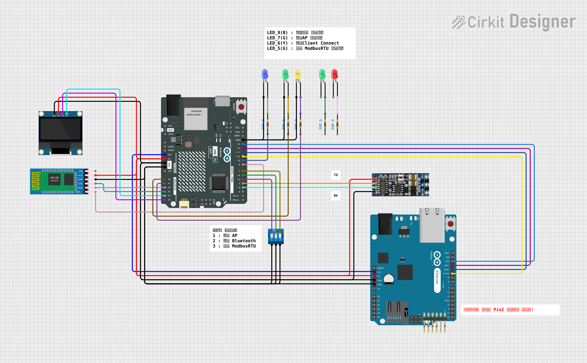

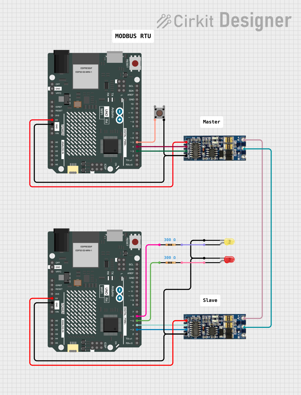
Explore Projects Built with ARDUINO UNO R4 WIFI
Common Applications and Use Cases
- IoT projects, such as smart home devices and environmental monitoring systems
- Prototyping and testing of wireless communication systems
- Educational purposes for learning microcontroller programming and IoT concepts
- Remote data logging and control systems
- Robotics and automation projects
Technical Specifications
The Arduino UNO R4 WIFI offers a range of features and specifications that make it a powerful and flexible development platform.
Key Technical Details
| Specification | Value |
|---|---|
| Microcontroller | ATmega4809 |
| Operating Voltage | 5V |
| Input Voltage (recommended) | 7-12V |
| Input Voltage (limit) | 6-24V |
| Digital I/O Pins | 14 (6 PWM outputs) |
| Analog Input Pins | 6 |
| Flash Memory | 48 KB (ATmega4809) |
| SRAM | 6 KB |
| EEPROM | 256 bytes |
| Clock Speed | 16 MHz |
| Wi-Fi Module | ESP32-S3 |
| USB Interface | USB-C |
| Dimensions | 68.6 mm x 53.4 mm |
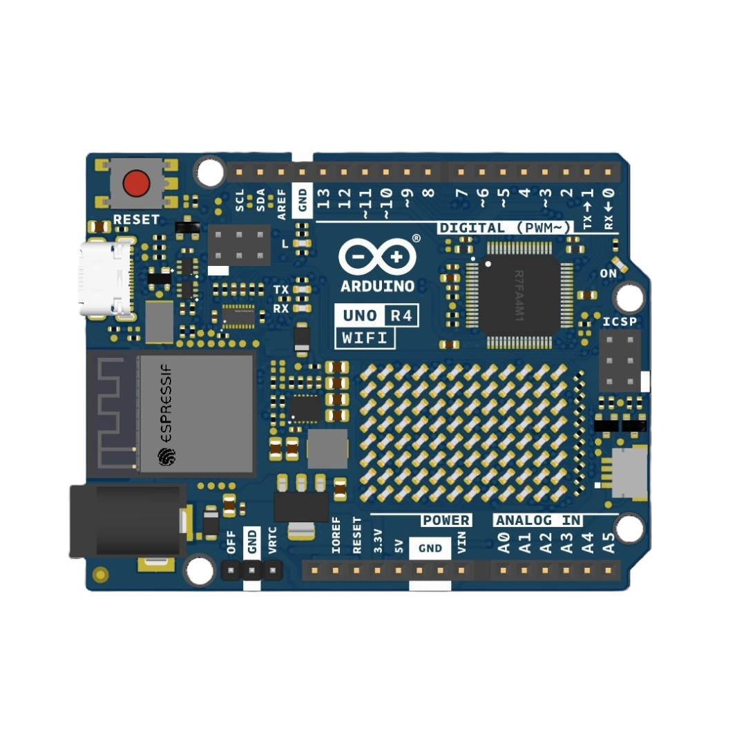
Pin Configuration and Descriptions
The Arduino UNO R4 WIFI features a standard pinout similar to other Arduino UNO boards, with additional pins for Wi-Fi functionality.
Digital and Power Pins
| Pin Number | Pin Name | Description |
|---|---|---|
| D0-D13 | Digital I/O | General-purpose digital input/output pins |
| A0-A5 | Analog Input | Analog input pins (10-bit resolution) |
| VIN | VIN | Input voltage to the board (7-12V) |
| 5V | 5V | Regulated 5V output |
| 3.3V | 3.3V | Regulated 3.3V output |
| GND | Ground | Ground pins |
| RESET | Reset | Resets the microcontroller |
Wi-Fi and Communication Pins
| Pin Name | Description |
|---|---|
| TX (D1) | UART Transmit (for serial communication) |
| RX (D0) | UART Receive (for serial communication) |
| SDA | I2C Data Line |
| SCL | I2C Clock Line |
| SPI Pins | MOSI, MISO, SCK (for SPI communication) |
| ESP32-S3 | Wi-Fi module pins (internally connected) |
Usage Instructions
The Arduino UNO R4 WIFI is easy to use and compatible with the Arduino IDE. Follow these steps to get started:
Setting Up the Board
- Install the Arduino IDE: Download and install the latest version of the Arduino IDE from the official Arduino website.
- Connect the Board: Use a USB-C cable to connect the UNO R4 WIFI to your computer.
- Select the Board and Port:
- Open the Arduino IDE.
- Go to
Tools > Boardand select "Arduino UNO R4 WIFI." - Go to
Tools > Portand select the appropriate COM port.
- Install Required Libraries:
- For Wi-Fi functionality, install the
WiFilibrary from the Arduino Library Manager.
- For Wi-Fi functionality, install the
Example: Connecting to Wi-Fi
The following example demonstrates how to connect the Arduino UNO R4 WIFI to a Wi-Fi network.
#include <WiFi.h> // Include the WiFi library for ESP32-S3 module

const char* ssid = "Your_SSID";       // Replace with your Wi-Fi network name
const char* password = "Your_Password"; // Replace with your Wi-Fi password

void setup() {
  Serial.begin(115200); // Initialize serial communication for debugging
  delay(1000);          // Wait for serial monitor to initialize

  Serial.println("Connecting to Wi-Fi...");
  WiFi.begin(ssid, password); // Start Wi-Fi connection

  while (WiFi.status() != WL_CONNECTED) {
    delay(500); // Wait for connection
    Serial.print(".");
  }

  Serial.println("\nConnected to Wi-Fi!");
  Serial.print("IP Address: ");
  Serial.println(WiFi.localIP()); // Print the assigned IP address
}

void loop() {
  // Add your main code here
}
Important Considerations and Best Practices
- Power Supply: Ensure the board is powered within the recommended voltage range (7-12V) to avoid damage.
- Wi-Fi Signal Strength: Place the board within range of your Wi-Fi router for a stable connection.
- Library Compatibility: Use the latest versions of libraries to ensure compatibility with the UNO R4 WIFI.
- Static Discharge: Handle the board carefully to avoid damage from static electricity.
Troubleshooting and FAQs
Common Issues and Solutions
The board is not detected by the Arduino IDE:
- Ensure the correct USB-C cable is used (data-capable, not charge-only).
- Check if the correct board and port are selected in the Arduino IDE.
- Install the necessary drivers if prompted by your operating system.
Wi-Fi connection fails:
- Double-check the SSID and password for your Wi-Fi network.
- Ensure the Wi-Fi network is 2.4 GHz, as some modules may not support 5 GHz networks.
- Restart the board and try reconnecting.
Sketch upload fails:
- Press the reset button on the board and try uploading the sketch again.
- Ensure no other application is using the COM port.
FAQs
Q: Can I use the UNO R4 WIFI with 3.3V sensors?
A: Yes, the board provides a 3.3V output pin for powering 3.3V sensors. However, ensure the sensor's logic levels are compatible with the 5V I/O pins.
Q: Is the UNO R4 WIFI backward compatible with UNO R3 shields?
A: Yes, the UNO R4 WIFI maintains the same form factor and pinout as the UNO R3, ensuring compatibility with most shields.
Q: How do I update the firmware of the ESP32-S3 module?
A: Firmware updates can be performed using the Arduino IDE or other ESP32-specific tools. Refer to the official Arduino documentation for detailed instructions.
Q: Can I use the board for Bluetooth communication?
A: Yes, the ESP32-S3 module supports Bluetooth, but additional libraries may be required to enable this functionality.
By following this documentation, you can effectively utilize the Arduino UNO R4 WIFI for your IoT and prototyping projects.