How to Use 2P Contactor: Examples, Pinouts, and Specs
Documentation for 2P Contactor: BAOMAIN HC1-20/20 110V
1. Introduction
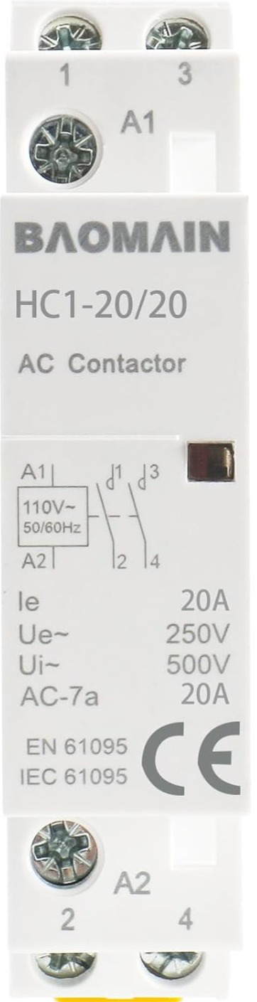
The BAOMAIN HC1-20/20 110V is a 2P (two-pole) contactor designed for controlling electrical circuits in industrial and automation applications. This electromechanical switch is capable of opening or closing circuits to manage power delivery to devices such as motors, lighting systems, and heating elements. Its robust design ensures reliable operation in demanding environments.
Common Applications:
- Motor Control: Start/stop control of single-phase or three-phase motors.
- Lighting Systems: Switching high-power lighting circuits.
- HVAC Systems: Controlling heating, ventilation, and air conditioning equipment.
- Industrial Automation: Power management in automated systems.
- Power Distribution: Switching and isolating power circuits.
2. Technical Specifications
The following table outlines the key technical details of the BAOMAIN HC1-20/20 110V contactor:
General Specifications
| Parameter | Value |
|---|---|
| Manufacturer | BAOMAIN |
| Part Number | HC1-20/20 110V |
| Type | 2P (Two-Pole) Contactor |
| Rated Voltage (Coil) | 110V AC |
| Rated Current (Load) | 20A |
| Rated Voltage (Load) | Up to 690V AC |
| Frequency | 50/60 Hz |
| Mechanical Life | 1,000,000 operations |
| Electrical Life | 100,000 operations |
| Mounting Type | DIN Rail or Panel Mount |
| Operating Temperature | -5°C to +40°C |
| Insulation Resistance | ≥10 MΩ |
Pin Configuration and Descriptions
| Pin/Terminal | Description |
|---|---|
| A1, A2 | Coil terminals for energizing the contactor (110V AC) |
| 1L1, 3L2 | Input terminals for the load circuit (Line side) |
| 2T1, 4T2 | Output terminals for the load circuit (Load side) |
| Auxiliary Contacts (Optional) | For control or signaling circuits (if equipped) |
3. Usage Instructions
How to Use the BAOMAIN HC1-20/20 110V Contactor in a Circuit
Power Supply to the Coil:
- Connect the coil terminals (A1 and A2) to a 110V AC power source. This energizes the contactor and closes the main contacts.
Load Connection:
- Connect the input power lines to terminals 1L1 and 3L2.
- Connect the load (e.g., motor, lighting system) to terminals 2T1 and 4T2.
Control Circuit (Optional):
- If the contactor includes auxiliary contacts, use them for control or signaling purposes (e.g., to indicate the contactor's state).
Mounting:
- Secure the contactor to a DIN rail or panel using the provided mounting options.
Important Considerations and Best Practices
- Voltage Compatibility: Ensure the coil voltage (110V AC) matches the power supply.
- Current Rating: Verify that the load current does not exceed the contactor's rated current (20A).
- Overload Protection: Use appropriate fuses or circuit breakers to protect the contactor and connected devices.
- Wiring: Use properly rated wires and ensure all connections are secure.
- Environment: Avoid exposure to excessive moisture, dust, or extreme temperatures.
4. Example Circuit with Arduino UNO
The BAOMAIN HC1-20/20 110V contactor can be controlled using an Arduino UNO and a relay module. Below is an example circuit and code to control the contactor.
Circuit Description:
- The Arduino controls a relay module, which in turn energizes the contactor's coil (A1 and A2).
- The contactor switches a load (e.g., a motor or light) connected to terminals 1L1, 3L2, 2T1, and 4T2.
Required Components:
- Arduino UNO
- 5V Relay Module
- BAOMAIN HC1-20/20 110V Contactor
- 110V AC Power Supply
- Load (e.g., motor or light)
- Jumper Wires
Arduino Code:
// Define the pin connected to the relay module
const int relayPin = 7;

void setup() {
  // Set the relay pin as an output
  pinMode(relayPin, OUTPUT);

  // Ensure the relay is off at startup
  digitalWrite(relayPin, LOW);
}

void loop() {
  // Turn the relay (and contactor) ON
  digitalWrite(relayPin, HIGH);
  delay(5000); // Keep the contactor ON for 5 seconds

  // Turn the relay (and contactor) OFF
  digitalWrite(relayPin, LOW);
  delay(5000); // Keep the contactor OFF for 5 seconds
}
Notes:
- Ensure the relay module is rated for 110V AC to safely control the contactor's coil.
- Use proper isolation techniques to separate the Arduino's low-voltage circuit from the high-voltage contactor circuit.
5. Troubleshooting and FAQs
Common Issues and Solutions
| Issue | Possible Cause | Solution |
|---|---|---|
| Contactor does not energize | Coil voltage is incorrect or not supplied | Verify the coil voltage (110V AC) |
| Load does not receive power | Loose connections or faulty wiring | Check and secure all connections |
| Contactor buzzes when energized | Voltage fluctuations or damaged coil | Ensure stable voltage; replace the coil if needed |
| Overheating of the contactor | Overloaded circuit or poor ventilation | Reduce load current; improve ventilation |
Frequently Asked Questions
Can I use this contactor with a DC load?
- No, the BAOMAIN HC1-20/20 is designed for AC loads only.
What is the maximum load current?
- The contactor is rated for a maximum load current of 20A.
Can I mount the contactor horizontally?
- Yes, the contactor can be mounted in any orientation, but ensure proper ventilation.
Does the contactor include auxiliary contacts?
- Auxiliary contacts are optional and may not be included in all models. Check the product specifications.
This documentation provides a comprehensive guide to using the BAOMAIN HC1-20/20 110V 2P contactor. For further assistance, refer to the manufacturer's datasheet or contact technical support.
Explore Projects Built with 2P Contactor


Explore Projects Built with 2P Contactor