Cirkit Designer
Your all-in-one circuit design IDE
Home /
Component Documentation
How to Use Buzzer: Examples, Pinouts, and Specs
Introduction
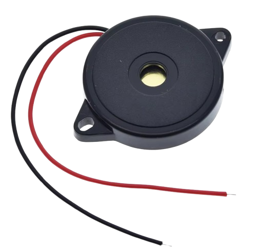
A buzzer is an audio signaling device that produces a buzzing sound when an electric current is applied. It is commonly used in alarms, timers, and confirmation of user input in electronic devices. Buzzers are essential components in various applications due to their simplicity, reliability, and ease of integration into electronic circuits.
Explore Projects Built with Buzzer
Arduino UNO Controlled School Bell System with DS3231 RTC and Relay Module

This circuit is designed as an automatic school bell system controlled by an Arduino UNO microcontroller. The Arduino is programmed to ring a buzzer at the start of each school period, with a total of 6 periods defined in the code. The DS3231 Real-Time Clock (RTC) module is used for accurate timekeeping, and a relay module interfaces the Arduino with the buzzer to handle the higher current required to drive the buzzer.
Battery-Powered IR Sensor and Buzzer Alarm System
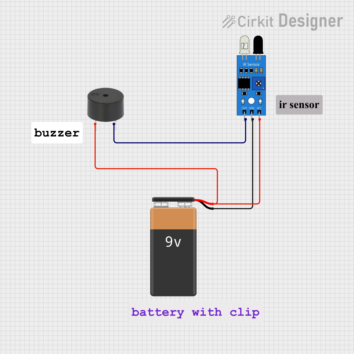
This circuit consists of an IR sensor and a buzzer powered by a 9V battery. The IR sensor detects an object and triggers the buzzer to sound an alarm when an object is detected.
Battery-Powered Buzzer Circuit
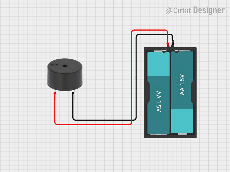
This circuit consists of a simple buzzer connected to a 3V battery source. The positive terminal of the battery is connected to the buzzer's power input, and the negative terminal is connected to the buzzer's ground. The circuit is designed to power the buzzer continuously, producing a constant sound or tone as long as the battery provides sufficient voltage.
Voice-Controlled Buzzer System with VC-02 Module

This circuit features a VC-02 voice recognition module connected to a buzzer and powered by a 5V battery. The VC-02 module is programmed to listen for specific voice commands and, upon recognizing the command 'can you make a sound', it activates the buzzer for one second. The circuit is designed for voice-activated sound generation, with the VC-02 module handling voice recognition and serial communication, and the buzzer providing audible feedback.
Explore Projects Built with Buzzer
Arduino UNO Controlled School Bell System with DS3231 RTC and Relay Module
This circuit is designed as an automatic school bell system controlled by an Arduino UNO microcontroller. The Arduino is programmed to ring a buzzer at the start of each school period, with a total of 6 periods defined in the code. The DS3231 Real-Time Clock (RTC) module is used for accurate timekeeping, and a relay module interfaces the Arduino with the buzzer to handle the higher current required to drive the buzzer.
Battery-Powered IR Sensor and Buzzer Alarm System
This circuit consists of an IR sensor and a buzzer powered by a 9V battery. The IR sensor detects an object and triggers the buzzer to sound an alarm when an object is detected.
Battery-Powered Buzzer Circuit
This circuit consists of a simple buzzer connected to a 3V battery source. The positive terminal of the battery is connected to the buzzer's power input, and the negative terminal is connected to the buzzer's ground. The circuit is designed to power the buzzer continuously, producing a constant sound or tone as long as the battery provides sufficient voltage.
Voice-Controlled Buzzer System with VC-02 Module
This circuit features a VC-02 voice recognition module connected to a buzzer and powered by a 5V battery. The VC-02 module is programmed to listen for specific voice commands and, upon recognizing the command 'can you make a sound', it activates the buzzer for one second. The circuit is designed for voice-activated sound generation, with the VC-02 module handling voice recognition and serial communication, and the buzzer providing audible feedback.
Technical Specifications
Key Technical Details
| Parameter | Value |
|---|---|
| Operating Voltage | 3V to 12V |
| Current Consumption | 10mA to 30mA |
| Sound Output | 85dB at 10cm |
| Frequency Range | 2kHz to 4kHz |
| Operating Temperature | -20°C to +60°C |
| Dimensions | 12mm diameter, 9mm height |
Pin Configuration and Descriptions
| Pin Number | Pin Name | Description |
|---|---|---|
| 1 | VCC | Positive voltage supply (3V to 12V) |
| 2 | GND | Ground |
Usage Instructions
How to Use the Buzzer in a Circuit
- Power Supply: Connect the VCC pin of the buzzer to the positive terminal of the power supply (3V to 12V).
- Ground Connection: Connect the GND pin of the buzzer to the ground terminal of the power supply.
- Control Signal: If using a microcontroller (e.g., Arduino), connect the VCC pin to a digital output pin of the microcontroller to control the buzzer.
Important Considerations and Best Practices
- Voltage Range: Ensure the operating voltage is within the specified range (3V to 12V) to avoid damaging the buzzer.
- Current Limiting: Use a current-limiting resistor if necessary to prevent excessive current flow.
- Mounting: Secure the buzzer properly in the circuit to avoid mechanical vibrations affecting the sound output.
- Polarity: Observe correct polarity when connecting the buzzer to the power supply.
Example Circuit with Arduino UNO
Below is an example of how to connect and control a buzzer using an Arduino UNO:
Circuit Diagram
Arduino UNO       Buzzer
-----------       ------
Pin 8 ----------- VCC
GND ------------- GND
Arduino Code
// Buzzer connected to digital pin 8
const int buzzerPin = 8;

void setup() {
  // Initialize the buzzer pin as an output
  pinMode(buzzerPin, OUTPUT);
}

void loop() {
  // Turn the buzzer on
  digitalWrite(buzzerPin, HIGH);
  delay(1000); // Wait for 1 second

  // Turn the buzzer off
  digitalWrite(buzzerPin, LOW);
  delay(1000); // Wait for 1 second
}
Troubleshooting and FAQs
Common Issues Users Might Face
No Sound Output:
- Solution: Check the power supply connections and ensure the voltage is within the specified range. Verify that the control signal from the microcontroller is correctly configured.
Low Sound Volume:
- Solution: Ensure the operating voltage is at the higher end of the specified range (e.g., 12V) for maximum sound output. Check for any obstructions or mechanical issues affecting the buzzer.
Intermittent Sound:
- Solution: Verify the stability of the power supply and ensure there are no loose connections. Check the control signal for any irregularities.
FAQs
Can I use the buzzer with a 5V power supply?
- Yes, the buzzer can operate within a voltage range of 3V to 12V, so a 5V power supply is suitable.
How do I control the buzzer with an Arduino?
- Connect the VCC pin of the buzzer to a digital output pin of the Arduino and the GND pin to the ground. Use the
digitalWritefunction to control the buzzer.
- Connect the VCC pin of the buzzer to a digital output pin of the Arduino and the GND pin to the ground. Use the
What is the typical current consumption of the buzzer?
- The current consumption typically ranges from 10mA to 30mA, depending on the operating voltage.
By following this documentation, users can effectively integrate and troubleshoot a buzzer in their electronic projects.