How to Use AVR32DA32: Examples, Pinouts, and Specs
Introduction
The AVR32DA32 is a 32-bit microcontroller developed by Microchip Technology. It is part of the AVR DA family, designed for low-power and high-performance applications. This microcontroller is built on the AVR architecture and integrates a variety of peripherals, including Analog-to-Digital Converters (ADCs), timers, and communication interfaces such as UART, SPI, and I2C. Its versatility makes it ideal for embedded systems, IoT devices, industrial automation, and consumer electronics.
Explore Projects Built with AVR32DA32
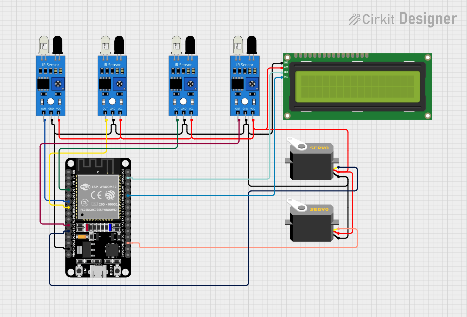
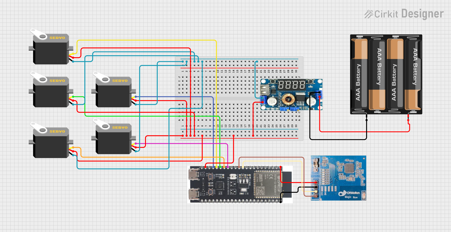
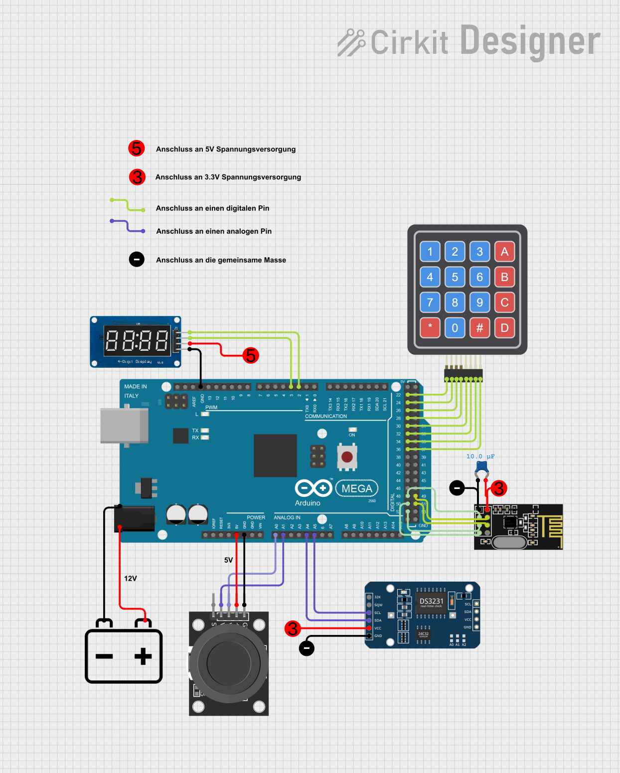
Explore Projects Built with AVR32DA32
Common Applications
- IoT devices and smart home systems
- Industrial control and automation
- Consumer electronics
- Data acquisition systems
- Low-power portable devices
Technical Specifications
Key Technical Details
| Parameter | Value |
|---|---|
| Architecture | 32-bit AVR |
| Operating Voltage | 1.8V to 5.5V |
| Flash Memory | 32 KB |
| SRAM | 4 KB |
| EEPROM | 256 Bytes |
| Clock Speed | Up to 24 MHz |
| ADC Resolution | 12-bit |
| Communication Interfaces | UART, SPI, I2C, LIN, USART |
| Timers | 16-bit and 8-bit timers |
| GPIO Pins | 28 |
| Operating Temperature Range | -40°C to +125°C |
| Package Options | TQFP, QFN |
Pin Configuration and Descriptions
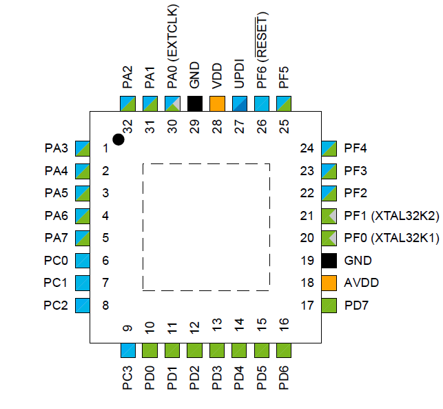
The AVR32DA32 comes in a 32-pin package. Below is the pin configuration and description:
| Pin Number | Pin Name | Description |
|---|---|---|
| 1 | VDD | Positive supply voltage |
| 2 | GND | Ground |
| 3 | PA0 | GPIO/Analog input/Peripheral function |
| 4 | PA1 | GPIO/Analog input/Peripheral function |
| 5 | PA2 | GPIO/Analog input/Peripheral function |
| 6 | PA3 | GPIO/Analog input/Peripheral function |
| 7 | PB0 | GPIO/Peripheral function |
| 8 | PB1 | GPIO/Peripheral function |
| 9 | PB2 | GPIO/Peripheral function |
| 10 | PB3 | GPIO/Peripheral function |
| ... | ... | ... |
| 32 | RESET | Reset pin |
Note: Refer to the official datasheet for the complete pinout and alternate functions.
Usage Instructions
How to Use the AVR32DA32 in a Circuit
Power Supply:
- Connect the VDD pin to a regulated power supply (1.8V to 5.5V).
- Connect the GND pin to the ground of the circuit.
Clock Configuration:
- Use an external crystal oscillator or the internal clock source.
- Configure the clock settings in the firmware to achieve the desired frequency.
Programming:
- Use an In-System Programmer (ISP) or a debugger such as Microchip's MPLAB PICkit 4.
- Connect the programming pins (e.g., MISO, MOSI, SCK, RESET) to the programmer.
Peripheral Configuration:
- Configure GPIO pins as input or output in the firmware.
- Initialize communication interfaces (UART, SPI, I2C) as needed.
Example Circuit:
- Connect an LED to a GPIO pin with a current-limiting resistor.
- Use a push button connected to another GPIO pin for input.
Important Considerations and Best Practices
- Decouple the power supply with capacitors (e.g., 0.1 µF and 10 µF) close to the VDD pin.
- Avoid leaving unused pins floating; configure them as inputs with pull-up resistors or as outputs.
- Ensure proper grounding to minimize noise and interference.
- Use appropriate ESD protection for sensitive pins.
Example Code for Arduino UNO Integration
The AVR32DA32 can communicate with an Arduino UNO via UART. Below is an example of how to send data from the AVR32DA32 to the Arduino UNO:
// AVR32DA32 UART Configuration Example
#include <avr/io.h>

void UART_init(void) {
    // Set baud rate to 9600
    uint16_t baud = (F_CPU / (16 * 9600)) - 1;
    UBRR0H = (baud >> 8);  // Set high byte of baud rate
    UBRR0L = baud;         // Set low byte of baud rate

    // Enable transmitter
    UCSR0B = (1 << TXEN0);

    // Set frame format: 8 data bits, no parity, 1 stop bit
    UCSR0C = (1 << UCSZ01) | (1 << UCSZ00);
}

void UART_sendChar(char data) {
    // Wait for the transmit buffer to be empty
    while (!(UCSR0A & (1 << UDRE0)));
    // Load data into the transmit buffer
    UDR0 = data;
}

int main(void) {
    UART_init();  // Initialize UART

    while (1) {
        UART_sendChar('H');  // Send character 'H'
        UART_sendChar('i');  // Send character 'i'
        UART_sendChar('\n'); // Send newline character
        _delay_ms(1000);     // Wait 1 second
    }
}
Note: Replace
F_CPUwith the clock frequency of the AVR32DA32 (e.g., 16 MHz).
Troubleshooting and FAQs
Common Issues and Solutions
Microcontroller Not Responding:
- Verify the power supply voltage and connections.
- Check the RESET pin; ensure it is not held low.
Programming Failure:
- Ensure the programmer is correctly connected to the programming pins.
- Verify that the correct microcontroller is selected in the programming software.
Peripheral Not Working:
- Double-check the pin configuration in the firmware.
- Ensure the peripheral clock is enabled in the firmware.
Excessive Power Consumption:
- Check for floating input pins; configure them properly.
- Use low-power modes when the microcontroller is idle.
FAQs
Q: Can the AVR32DA32 operate at 5V?
A: Yes, the AVR32DA32 supports an operating voltage range of 1.8V to 5.5V.
Q: Does the AVR32DA32 have an internal oscillator?
A: Yes, it includes an internal oscillator that can be used as the clock source.
Q: How do I protect the microcontroller from ESD?
A: Use ESD protection diodes and ensure proper grounding in your circuit design.
Q: Can I use the AVR32DA32 for battery-powered applications?
A: Yes, its low-power features make it suitable for battery-powered devices.