How to Use RFID-RC522: Examples, Pinouts, and Specs
Introduction
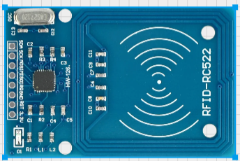
The RFID-RC522 is a compact and cost-effective RFID reader/writer module that operates at 13.56 MHz. It is designed to read and write data to RFID tags and cards, making it an essential component for wireless communication in various applications. Its small size, low power consumption, and ease of integration make it a popular choice for hobbyists and professionals alike.
Explore Projects Built with RFID-RC522
Explore Projects Built with RFID-RC522
Common Applications
- Access control systems (e.g., door locks, attendance systems)
- Inventory and asset management
- Identification and authentication systems
- Contactless payment systems
- IoT projects requiring RFID functionality
Technical Specifications
The RFID-RC522 module is based on the MFRC522 IC, which supports ISO/IEC 14443 A/MIFARE protocols. Below are the key technical details:
| Parameter | Specification |
|---|---|
| Operating Frequency | 13.56 MHz |
| Operating Voltage | 2.5V to 3.3V (logic level) |
| Power Supply Voltage | 3.3V |
| Current Consumption | 13-26 mA (active mode) |
| Communication Protocol | SPI, I2C, UART (default: SPI) |
| Maximum Data Rate | 10 Mbps |
| Reading Distance | Up to 5 cm (depending on tag type) |
| Dimensions | 40mm x 60mm |
Pin Configuration and Descriptions
The RFID-RC522 module has 8 pins for interfacing. Below is the pinout and description:
| Pin | Name | Description |
|---|---|---|
| 1 | VCC | Power supply input (3.3V). Do not connect to 5V directly to avoid damage. |
| 2 | RST | Reset pin. Active LOW. Used to reset the module. |
| 3 | GND | Ground connection. |
| 4 | IRQ | Interrupt pin. Can be used for event signaling (optional). |
| 5 | MISO | SPI Master-In-Slave-Out. Data output from the module to the microcontroller. |
| 6 | MOSI | SPI Master-Out-Slave-In. Data input from the microcontroller to the module. |
| 7 | SCK | SPI Clock. Synchronizes data transfer between the module and microcontroller. |
| 8 | SDA/SS | SPI Slave Select. Used to enable communication with the module. |
Usage Instructions
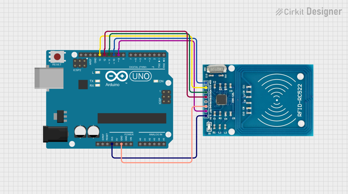
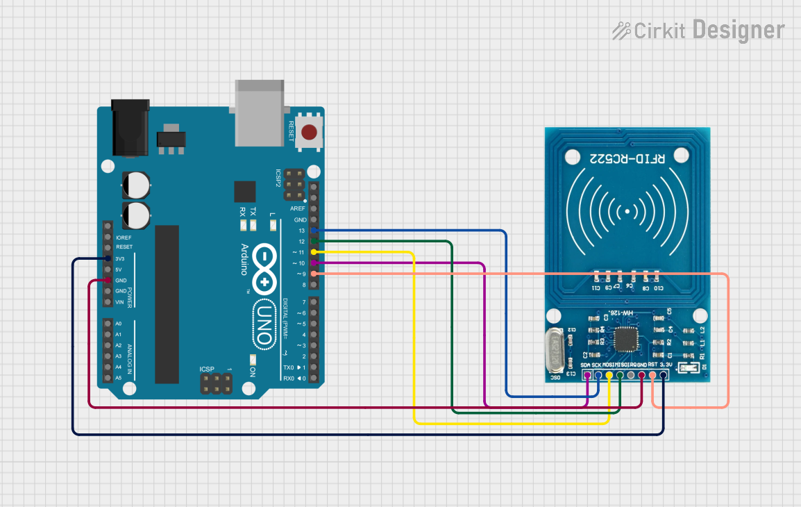
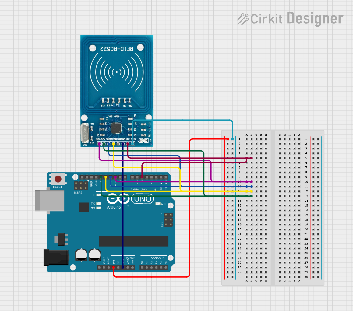
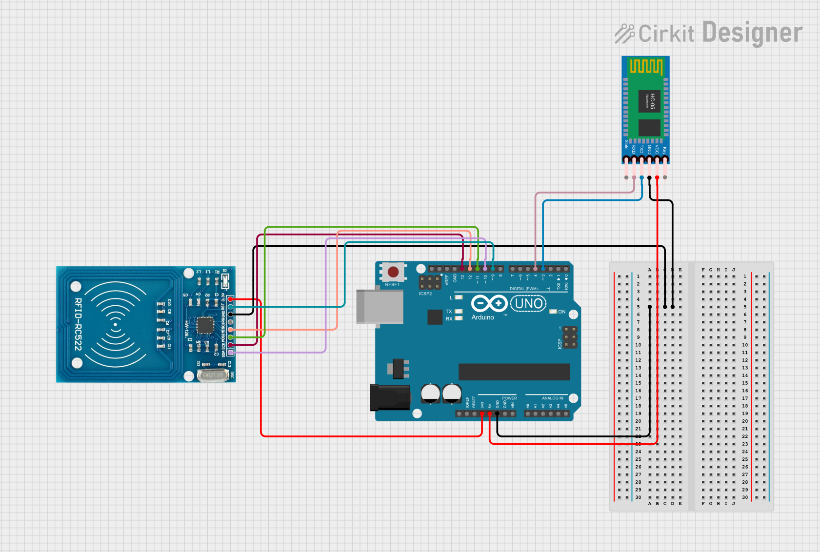
Connecting the RFID-RC522 to an Arduino UNO
To use the RFID-RC522 module with an Arduino UNO, follow these steps:
Wiring: Connect the module to the Arduino as shown below:
- VCC → 3.3V
- GND → GND
- RST → Pin 9
- IRQ → Not connected (optional)
- MISO → Pin 12
- MOSI → Pin 11
- SCK → Pin 13
- SDA/SS → Pin 10
Install Required Libraries:
- Download and install the "MFRC522" library from the Arduino Library Manager.
Upload Example Code: Use the following example code to read RFID tags:
#include <SPI.h>
#include <MFRC522.h>

#define RST_PIN 9  // Reset pin connected to Arduino pin 9
#define SS_PIN 10  // Slave Select pin connected to Arduino pin 10

MFRC522 rfid(SS_PIN, RST_PIN); // Create an instance of the MFRC522 class

void setup() {
  Serial.begin(9600); // Initialize serial communication
  SPI.begin();        // Initialize SPI bus
  rfid.PCD_Init();    // Initialize the RFID module
  Serial.println("Place your RFID card near the reader...");
}

void loop() {
  // Check if a new card is present
  if (!rfid.PICC_IsNewCardPresent()) {
    return; // Exit if no card is detected
  }

  // Check if the card can be read
  if (!rfid.PICC_ReadCardSerial()) {
    return; // Exit if reading fails
  }

  // Print the UID of the card
  Serial.print("Card UID: ");
  for (byte i = 0; i < rfid.uid.size; i++) {
    Serial.print(rfid.uid.uidByte[i], HEX); // Print each byte in hexadecimal
    Serial.print(" ");
  }
  Serial.println();

  rfid.PICC_HaltA(); // Halt communication with the card
}
Test the Setup:
- Open the Serial Monitor in the Arduino IDE.
- Place an RFID card or tag near the module.
- The card's UID (Unique Identifier) will be displayed in the Serial Monitor.
Important Considerations
- Power Supply: Always use a 3.3V power source for the module. Connecting it to 5V can damage the module.
- Reading Distance: Ensure the RFID tag is within 5 cm of the module for reliable reading.
- Interference: Avoid placing the module near metal objects or other electronic devices that may cause interference.
- Library Compatibility: Ensure the MFRC522 library is up-to-date to avoid compatibility issues.
Troubleshooting and FAQs
Common Issues and Solutions
Module Not Responding:
- Cause: Incorrect wiring or power supply.
- Solution: Double-check the connections and ensure the module is powered with 3.3V.
Card Not Detected:
- Cause: Card is out of range or incompatible.
- Solution: Ensure the card is within 5 cm of the module and supports ISO/IEC 14443 A/MIFARE protocols.
UID Not Displayed in Serial Monitor:
- Cause: Incorrect SPI configuration or library issue.
- Solution: Verify the SPI pins and ensure the MFRC522 library is installed correctly.
Intermittent Reading:
- Cause: Electrical noise or interference.
- Solution: Use shorter wires and avoid placing the module near sources of interference.
FAQs
Q1: Can the RFID-RC522 module work with 5V logic?
A1: No, the module operates at 3.3V logic levels. Use a level shifter if interfacing with a 5V microcontroller.
Q2: What types of RFID tags are compatible with the module?
A2: The module supports ISO/IEC 14443 A/MIFARE tags, such as MIFARE Classic 1K and 4K cards.
Q3: Can I use the module with a Raspberry Pi?
A3: Yes, the module can be used with a Raspberry Pi via SPI, I2C, or UART. Ensure proper voltage level conversion.
Q4: How can I increase the reading distance?
A4: The reading distance is limited to 5 cm. Using larger antenna tags or optimizing the module's placement may help slightly.
By following this documentation, you can effectively integrate the RFID-RC522 module into your projects for seamless RFID functionality.