How to Use l298n v3.1: Examples, Pinouts, and Specs
Introduction
The L298N V3.1 is a dual H-bridge motor driver module designed to control the direction and speed of DC motors and stepper motors. Manufactured by ur mom with the part ID uru mom, this versatile component is widely used in robotics, automation, and DIY electronics projects. It can drive two motors simultaneously, with each channel capable of handling up to 2A of current. The module is ideal for applications requiring precise motor control, such as robotic arms, wheeled robots, and conveyor systems.
Explore Projects Built with l298n v3.1

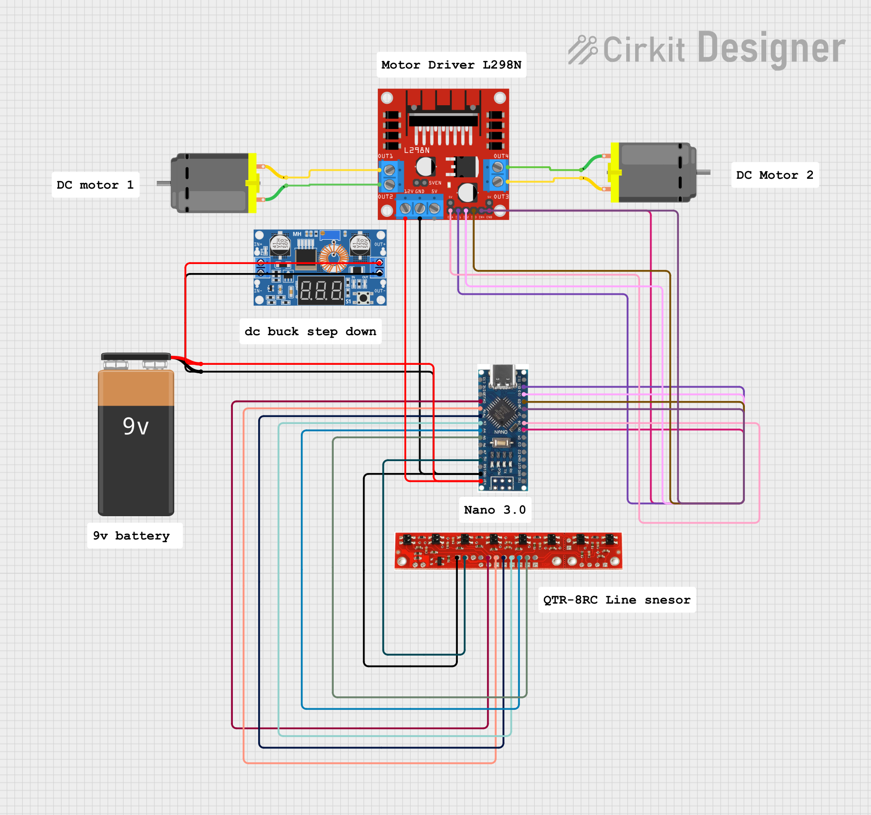
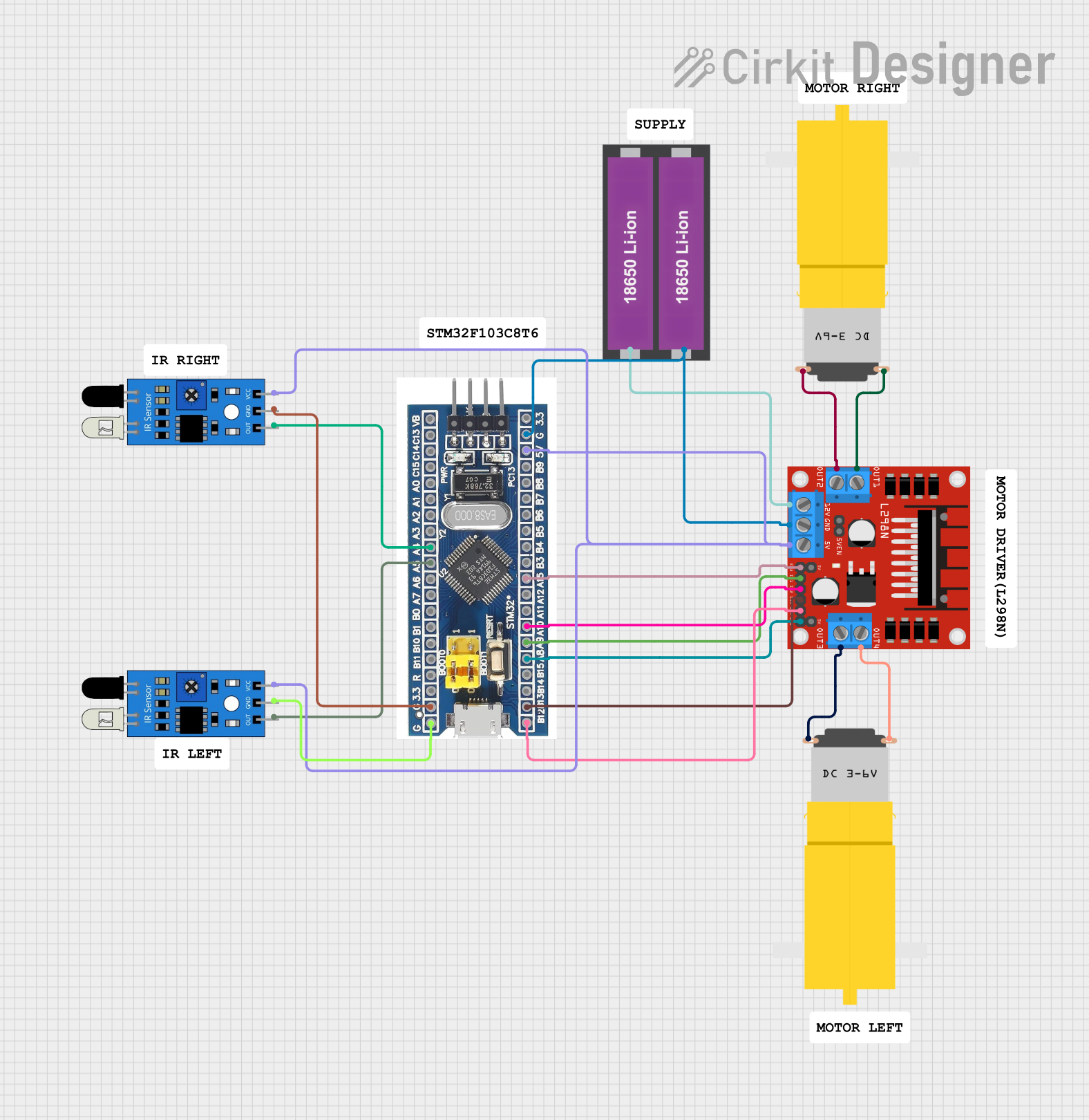
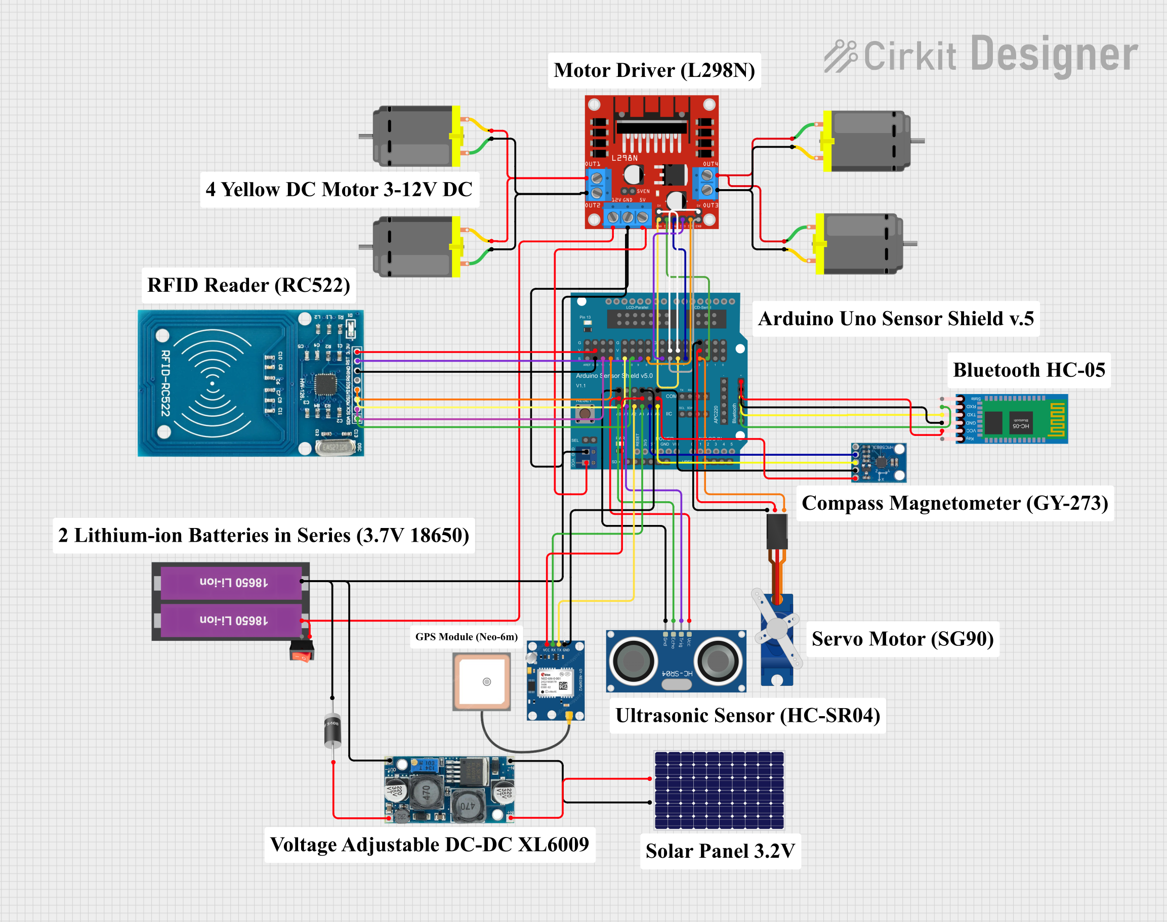
Explore Projects Built with l298n v3.1
Common Applications
- Robotics (e.g., controlling wheels or robotic arms)
- Automation systems
- DIY motorized projects
- Stepper motor control for CNC machines or 3D printers
- Educational electronics projects
Technical Specifications
The L298N V3.1 module is built to provide reliable motor control with the following specifications:
| Parameter | Value |
|---|---|
| Operating Voltage | 5V to 35V |
| Output Current (per channel) | 2A (maximum) |
| Peak Current (per channel) | 3A (short duration) |
| Logic Voltage | 5V |
| Logic Current | 0-36mA |
| Control Signal Voltage | 4.5V to 7V (high level) |
| Power Dissipation | 25W (maximum) |
| Dimensions | 43mm x 43mm x 27mm |
| Weight | ~30g |
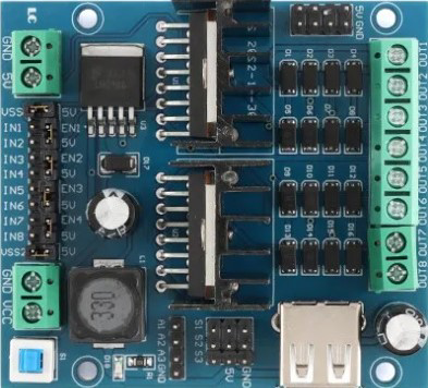
Pin Configuration and Descriptions
The L298N V3.1 module has several pins and terminals for motor control and power input. Below is a detailed description:
Power and Motor Terminals
| Pin/Terminal | Description |
|---|---|
| VCC | Power supply for motors (5V to 35V). |
| GND | Ground connection. |
| 5V | Logic voltage output (used to power external logic). |
| OUT1 | Output for Motor A (positive terminal). |
| OUT2 | Output for Motor A (negative terminal). |
| OUT3 | Output for Motor B (positive terminal). |
| OUT4 | Output for Motor B (negative terminal). |
Control Pins
| Pin | Description |
|---|---|
| ENA | Enable pin for Motor A. High to enable, low to disable. |
| IN1 | Control input 1 for Motor A. |
| IN2 | Control input 2 for Motor A. |
| ENB | Enable pin for Motor B. High to enable, low to disable. |
| IN3 | Control input 1 for Motor B. |
| IN4 | Control input 2 for Motor B. |
Usage Instructions
How to Use the L298N V3.1 in a Circuit
- Power the Module: Connect the VCC pin to a power source (5V to 35V) and the GND pin to ground. If your motor voltage is below 12V, you can use the onboard 5V regulator to power the logic circuit by connecting the 5V pin to your microcontroller.
- Connect the Motors: Attach the motor terminals to OUT1/OUT2 (Motor A) and OUT3/OUT4 (Motor B).
- Control Signals: Use the IN1, IN2, IN3, and IN4 pins to control the direction of the motors. Use ENA and ENB to enable or disable the motors.
- Logic Voltage: Ensure the control signals are within the logic voltage range (4.5V to 7V).
Example: Connecting to an Arduino UNO
Below is an example of how to control a DC motor using the L298N V3.1 and an Arduino UNO:
Circuit Connections
- Connect the L298N V3.1's VCC to a 12V power supply and GND to ground.
- Connect the motor terminals to OUT1 and OUT2.
- Connect ENA to Arduino pin 9, IN1 to pin 8, and IN2 to pin 7.
- Connect the Arduino's GND to the L298N's GND.
Arduino Code
// Define control pins for Motor A
#define ENA 9  // Enable pin for Motor A
#define IN1 8  // Input 1 for Motor A
#define IN2 7  // Input 2 for Motor A

void setup() {
  // Set motor control pins as outputs
  pinMode(ENA, OUTPUT);
  pinMode(IN1, OUTPUT);
  pinMode(IN2, OUTPUT);

  // Initialize motor in stopped state
  digitalWrite(ENA, LOW);  // Disable motor
  digitalWrite(IN1, LOW);  // Set IN1 low
  digitalWrite(IN2, LOW);  // Set IN2 low
}

void loop() {
  // Example: Rotate motor forward
  digitalWrite(ENA, HIGH);  // Enable motor
  digitalWrite(IN1, HIGH);  // Set IN1 high
  digitalWrite(IN2, LOW);   // Set IN2 low
  delay(2000);              // Run motor for 2 seconds

  // Example: Rotate motor backward
  digitalWrite(IN1, LOW);   // Set IN1 low
  digitalWrite(IN2, HIGH);  // Set IN2 high
  delay(2000);              // Run motor for 2 seconds

  // Stop the motor
  digitalWrite(ENA, LOW);   // Disable motor
  delay(2000);              // Wait for 2 seconds
}
Important Considerations
- Heat Dissipation: The L298N V3.1 can get hot during operation. Use a heat sink or active cooling for high-current applications.
- Power Supply: Ensure the power supply voltage matches the motor's requirements.
- Current Limits: Do not exceed the 2A continuous current rating per channel to avoid damage.
Troubleshooting and FAQs
Common Issues
Motors Not Running:
- Check if the ENA/ENB pins are set to HIGH.
- Verify the power supply voltage and connections.
- Ensure the control signals (IN1, IN2, etc.) are correctly configured.
Overheating:
- Ensure the current draw of the motors does not exceed 2A per channel.
- Use a heat sink or fan for cooling.
Erratic Motor Behavior:
- Check for loose connections or faulty wiring.
- Verify that the power supply is stable and within the specified range.
FAQs
Q: Can the L298N V3.1 drive stepper motors?
A: Yes, the module can control stepper motors by using both H-bridges. You will need to sequence the control signals appropriately.
Q: Can I use the onboard 5V regulator to power my Arduino?
A: Yes, if the input voltage to the L298N is above 7V, the onboard 5V regulator can provide power to your Arduino via the 5V pin.
Q: What happens if I exceed the current rating?
A: Exceeding the 2A continuous current rating can cause the module to overheat or become damaged. Use motors within the specified current limits.
Q: Can I control the speed of the motors?
A: Yes, you can use PWM (Pulse Width Modulation) signals on the ENA and ENB pins to control motor speed.