
How to Use LM2576 3 A Buck Regulator (TO-263-5): Examples, Pinouts, and Specs
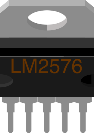
 Design with LM2576 3 A Buck Regulator (TO-263-5) in Cirkit Designer
Introduction
The LM2576 is a step-down (buck) voltage regulator capable of delivering up to 3 A of output current. It is designed for efficient power conversion and features a built-in switch, simplifying circuit design. With a wide input voltage range of 4 V to 40 V, the LM2576 is ideal for battery-powered devices, industrial power supplies, and other low-voltage applications. Its high efficiency and ease of use make it a popular choice for DC-DC conversion tasks.
Explore Projects Built with LM2576 3 A Buck Regulator (TO-263-5)
 Open Project in Cirkit Designer
 Open Project in Cirkit Designer
 Open Project in Cirkit Designer
 Open Project in Cirkit Designer
Explore Projects Built with LM2576 3 A Buck Regulator (TO-263-5)
Open Project in Cirkit DesignerOpen Project in Cirkit DesignerOpen Project in Cirkit DesignerOpen Project in Cirkit DesignerCommon Applications
- Battery-powered devices
- Industrial power supplies
- Automotive electronics
- Embedded systems
- Adjustable power supplies
Technical Specifications
Key Specifications
| Parameter | Value |
|---|---|
| Input Voltage Range | 4 V to 40 V |
| Output Voltage Options | 3.3 V, 5 V, 12 V, 15 V, Adjustable |
| Output Current | Up to 3 A |
| Efficiency | Up to 90% |
| Switching Frequency | 52 kHz (fixed) |
| Operating Temperature | -40°C to +125°C |
| Package Type | TO-263-5 |
Pin Configuration
The LM2576 is available in a TO-263-5 package. The pinout is as follows:
| Pin Number | Pin Name | Description |
|---|---|---|
| 1 | VIN | Input voltage (4 V to 40 V) |
| 2 | Output | Regulated output voltage |
| 3 | Ground | Ground connection |
| 4 | Feedback | Feedback pin for adjustable output voltage |
| 5 | ON/OFF | Enable/disable control (active low) |
Usage Instructions
How to Use the LM2576 in a Circuit
- Input Capacitor: Connect a low-ESR capacitor (e.g., 100 µF electrolytic) between the VIN pin and ground to stabilize the input voltage.
- Output Capacitor: Use a low-ESR capacitor (e.g., 330 µF electrolytic) between the Output pin and ground to ensure stable operation.
- Inductor Selection: Choose an inductor with a current rating higher than the maximum output current (e.g., 3.5 A) and an appropriate inductance value based on the desired output voltage.
- Diode: Use a Schottky diode (e.g., 1N5822) between the Output pin and ground to handle the switching current.
- Feedback Resistors: For adjustable output voltage, connect a resistor divider network to the Feedback pin. For fixed output versions, this pin is internally configured.
- ON/OFF Control: Connect the ON/OFF pin to ground to enable the regulator. Leave it floating or connect it to VIN to disable the regulator.
Example Circuit
Below is an example of a 5 V output circuit using the LM2576-5.0:
VIN (12 V) ----+---- Input Capacitor (100 µF) ----+---- LM2576 (VIN Pin)
               |                                 |
               +---- Inductor (100 µH) ----+---- Output Capacitor (330 µF)
                                           |
                                           +---- Schottky Diode (1N5822)
                                           |
                                           +---- 5 V Output
Arduino UNO Example Code
The LM2576 can be used to power an Arduino UNO. Below is an example code snippet to demonstrate how to monitor the input voltage using the Arduino's ADC:
// Define the analog pin connected to the voltage divider
const int voltagePin = A0;

// Voltage divider resistor values (in ohms)
const float R1 = 10000.0; // Resistor connected to VIN
const float R2 = 1000.0;  // Resistor connected to ground

void setup() {
  Serial.begin(9600); // Initialize serial communication
}

void loop() {
  int adcValue = analogRead(voltagePin); // Read ADC value
  float voltage = (adcValue * 5.0 / 1023.0) * ((R1 + R2) / R2);

  // Print the input voltage to the Serial Monitor
  Serial.print("Input Voltage: ");
  Serial.print(voltage);
  Serial.println(" V");

  delay(1000); // Wait for 1 second
}
Note: Ensure the voltage divider reduces the input voltage to a safe level (below 5 V) for the Arduino's ADC.
Important Considerations
- Use low-ESR capacitors to ensure stable operation and minimize output ripple.
- Ensure the inductor and diode are rated for the maximum output current.
- Keep the feedback and ground traces short to minimize noise.
- Use proper heat sinking for the LM2576, as it can generate heat under high load conditions.
Troubleshooting and FAQs
Common Issues and Solutions
High Output Ripple:
- Ensure low-ESR capacitors are used for both input and output.
- Verify the inductor value and current rating are appropriate for the application.
Overheating:
- Check for proper heat sinking or airflow around the LM2576.
- Ensure the input voltage is within the specified range.
No Output Voltage:
- Verify the ON/OFF pin is connected to ground to enable the regulator.
- Check all connections, especially the feedback resistor network for adjustable versions.
Output Voltage Too Low or Unstable:
- Inspect the feedback resistor values for adjustable versions.
- Ensure the input voltage is stable and within the specified range.
FAQs
Q: Can the LM2576 be used for negative voltage regulation?
A: No, the LM2576 is designed for step-down (buck) regulation and cannot generate negative voltages. For negative voltage regulation, consider using the LM2576-NEG series.
Q: What is the maximum input voltage for the LM2576?
A: The maximum input voltage is 40 V. Exceeding this value may damage the component.
Q: Can I use the LM2576 without a heatsink?
A: For low current applications, a heatsink may not be necessary. However, for higher currents (close to 3 A), proper heat dissipation is required to prevent overheating.
Q: Is the LM2576 suitable for powering microcontrollers?
A: Yes, the LM2576 is ideal for powering microcontrollers like Arduino, as it provides a stable and efficient DC output.