How to Use Adafruit NXP 9 DoF: Examples, Pinouts, and Specs
Introduction
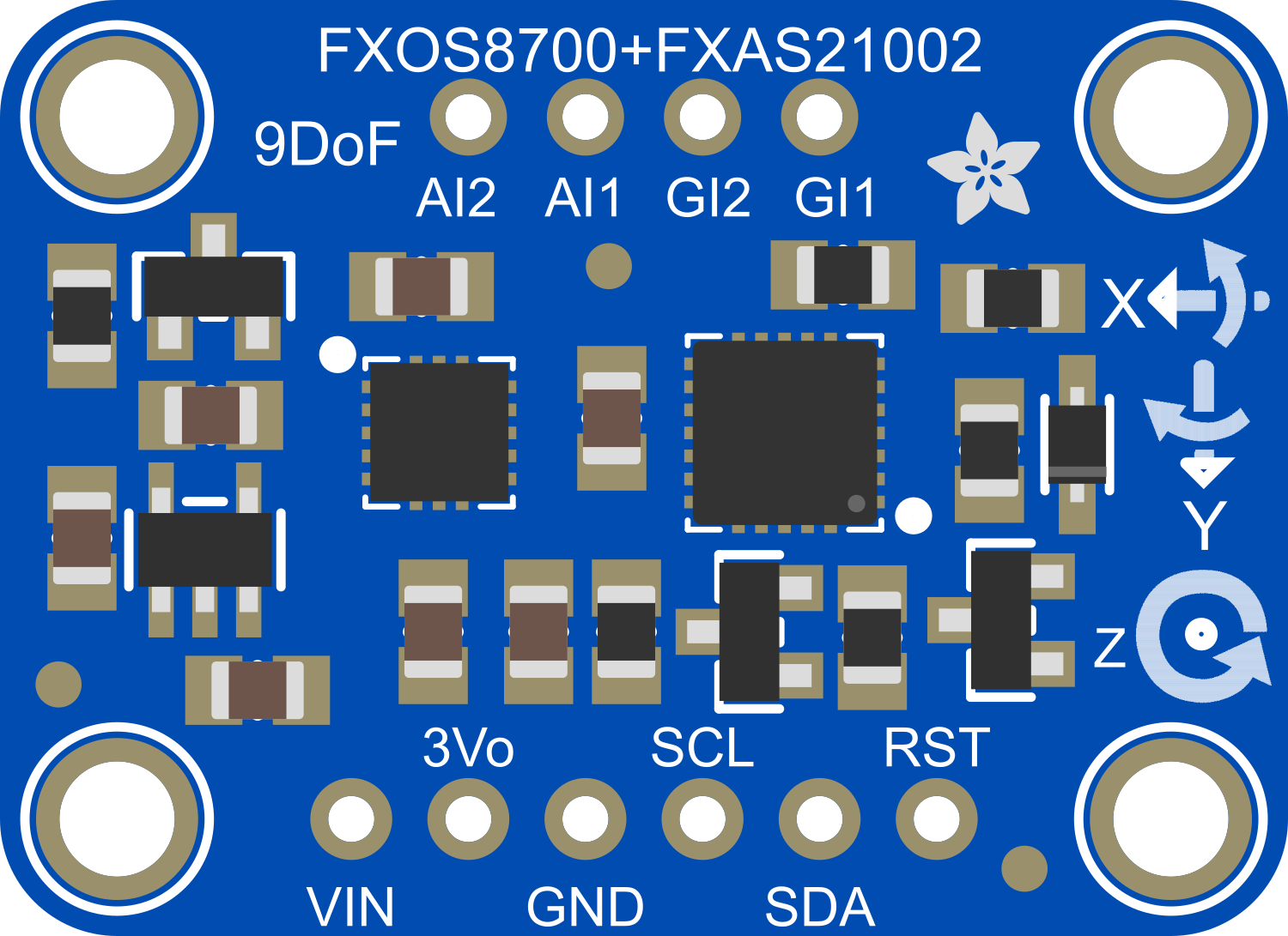
The Adafruit NXP 9 DoF is a compact, high-performance motion tracking module that combines three of the most important sensors for determining orientation and motion: a 3-axis accelerometer, a 3-axis magnetometer, and a 3-axis gyroscope. This sensor module is designed for easy integration with microcontrollers such as the Arduino UNO and uses the I2C communication protocol for data transfer. Common applications include orientation sensing in drones and mobile devices, motion tracking in virtual reality systems, and navigation assistance in robotics.
Explore Projects Built with Adafruit NXP 9 DoF
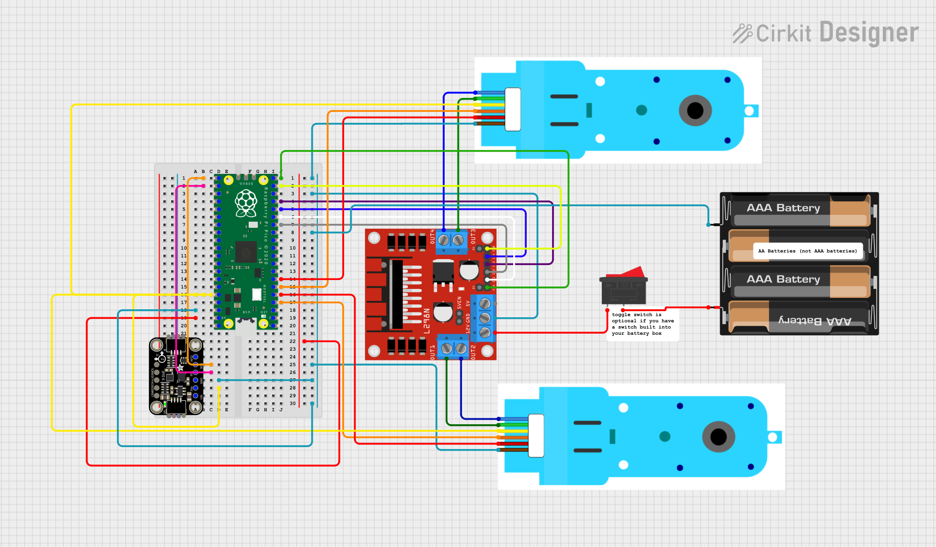


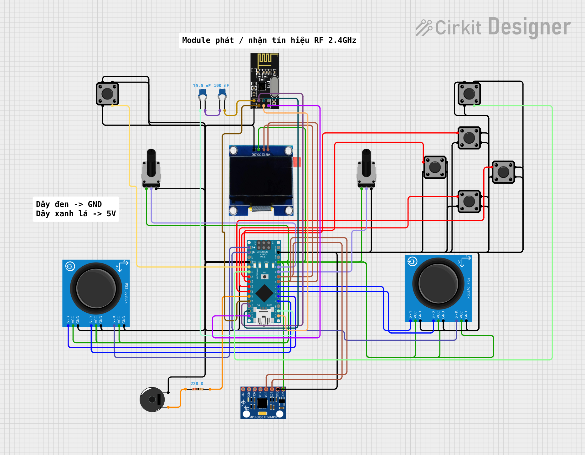
Explore Projects Built with Adafruit NXP 9 DoF
Technical Specifications
Key Features
- Accelerometer: Measures linear acceleration in three dimensions.
- Gyroscope: Measures angular velocity in three dimensions.
- Magnetometer: Measures magnetic fields, which can be used to determine heading relative to the Earth's magnetic North.
Electrical Characteristics
- Supply Voltage (VDD): 2.25V - 3.6V
- Interface Voltage (VDDIO): 1.7V - 3.6V
- Current Consumption: 10 μA in standby mode
Communication Interface
- Protocol: I2C (Inter-Integrated Circuit)
- I2C Address: 0x1D (default)
Environmental
- Operating Temperature Range: -40°C to +85°C
Pin Configuration and Descriptions
| Pin Number | Name | Description |
|---|---|---|
| 1 | VDD | Power supply voltage (2.25V - 3.6V) |
| 2 | GND | Ground connection |
| 3 | SDA | I2C data line |
| 4 | SCL | I2C clock line |
| 5 | INT | Interrupt output (active low) |
| 6 | ADDR | I2C address selection (float for default) |
Usage Instructions
Interfacing with Arduino
Connecting the Sensor:
- Connect VDD to the 3.3V output on the Arduino.
- Connect GND to a ground pin on the Arduino.
- Connect SDA to the A4 pin (SDA) on the Arduino UNO.
- Connect SCL to the A5 pin (SCL) on the Arduino UNO.
Library Installation:
- Install the Adafruit Sensor and Adafruit NXP 9 DoF libraries using the Arduino Library Manager.
Initialization:
- Initialize the sensor in your setup function and check for successful communication.
Reading Sensor Data:
- In the loop function, read the accelerometer, magnetometer, and gyroscope data.
Best Practices
- Use pull-up resistors on the I2C lines if they are not included on the breakout board.
- Ensure that the power supply is stable and within the specified voltage range.
- Avoid placing the sensor near strong magnetic fields to prevent interference with the magnetometer.
Example Code for Arduino
#include <Wire.h>
#include <Adafruit_Sensor.h>
#include <Adafruit_FXOS8700.h>
#include <Adafruit_FXAS21002C.h>

// Create sensor instances
Adafruit_FXOS8700 fxos8700 = Adafruit_FXOS8700();
Adafruit_FXAS21002C fxas21002c = Adafruit_FXAS21002C();

void setup() {
  Serial.begin(115200);
  // Wait for serial monitor to open
  while (!Serial) { delay(10); }

  // Initialize the sensors
  if(!fxos8700.begin(ACCEL_RANGE_2G)) {
    Serial.println("Failed to initialize accelerometer/magnetometer!");
    while(1);
  }
  if(!fxas21002c.begin(GYRO_RANGE_250DPS)) {
    Serial.println("Failed to initialize gyroscope!");
    while(1);
  }
}

void loop() {
  // Read the accelerometer & magnetometer
  sensors_event_t aevent, mevent;
  fxos8700.getEvent(&aevent, &mevent);

  // Read the gyroscope
  sensors_event_t gevent;
  fxas21002c.getEvent(&gevent);

  // Display the accelerometer & magnetometer results
  Serial.print("Accel X: "); Serial.print(aevent.acceleration.x); Serial.print(" ");
  Serial.print("Y: "); Serial.print(aevent.acceleration.y); Serial.print(" ");
  Serial.print("Z: "); Serial.print(aevent.acceleration.z); Serial.println(" m/s^2");

  // Display the magnetometer results (magnetic vector)
  Serial.print("Mag X: "); Serial.print(mevent.magnetic.x); Serial.print(" ");
  Serial.print("Y: "); Serial.print(mevent.magnetic.y); Serial.print(" ");
  Serial.print("Z: "); Serial.print(mevent.magnetic.z); Serial.println(" uT");

  // Display the gyroscope results (angular velocity)
  Serial.print("Gyro X: "); Serial.print(gevent.gyro.x); Serial.print(" ");
  Serial.print("Y: "); Serial.print(gevent.gyro.y); Serial.print(" ");
  Serial.print("Z: "); Serial.print(gevent.gyro.z); Serial.println(" dps");

  // Delay before the next reading
  delay(500);
}
Troubleshooting and FAQs
Common Issues
- Sensor Not Detected: Ensure that the wiring is correct and that the sensor is properly powered.
- Inaccurate Readings: Calibrate the sensor if possible, and make sure it's not affected by external magnetic fields.
- I2C Communication Errors: Check for loose connections and ensure pull-up resistors are in place if needed.
FAQs
Q: Can I change the I2C address of the sensor? A: Yes, the I2C address can be changed by connecting the ADDR pin to ground or VDD.
Q: How do I calibrate the magnetometer? A: Calibration typically involves rotating the sensor in various orientations. Refer to the sensor's datasheet for specific calibration procedures.
Q: What is the maximum I2C speed supported by the sensor? A: The sensor supports standard (100 kHz) and fast (400 kHz) I2C speeds.
For further assistance, consult the Adafruit NXP 9 DoF datasheet and the Adafruit support forums.