How to Use Adafruit Charlieplex 9x16 Green: Examples, Pinouts, and Specs
Introduction
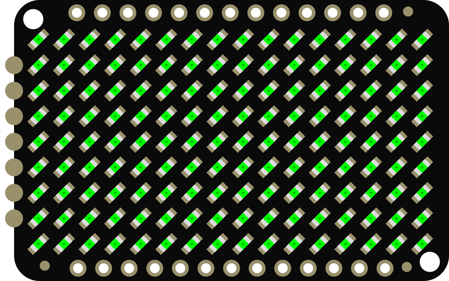
The Adafruit Charlieplex 9x16 Green is a compact and versatile LED matrix driver board designed to control a 9x16 grid of green LEDs, totaling 144 individual LEDs. This board utilizes the Charlieplexing technique to enable control of many LEDs with a minimal number of microcontroller pins. It is ideal for creating dynamic displays, animations, and indicators for projects where space and pin count are at a premium.
Explore Projects Built with Adafruit Charlieplex 9x16 Green

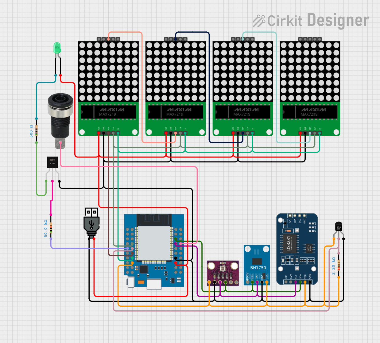


Explore Projects Built with Adafruit Charlieplex 9x16 Green
Common Applications and Use Cases
- Wearable electronics
- Small-scale message displays
- Battery-powered signs
- Decorative lighting
- Educational projects to demonstrate Charlieplexing
Technical Specifications
Key Technical Details
- Operating Voltage: 3.3V - 5V
- Maximum Current per LED: 20mA
- LED Wavelength: 565nm (Green)
- Communication Interface: I2C
- I2C Addresses: 0x70 (default) - 0x77 (selectable with solder jumpers)
Pin Configuration and Descriptions
| Pin Number | Name | Description |
|---|---|---|
| 1 | GND | Ground connection |
| 2 | VCC | Power supply (3.3V - 5V) |
| 3 | SDA | I2C Data line |
| 4 | SCL | I2C Clock line |
| 5 | ADDR | Address selection pin (connect to GND or VCC to change address) |
Usage Instructions
How to Use the Component in a Circuit
Power Connections: Connect the VCC pin to your power supply (3.3V - 5V) and the GND pin to the ground.
I2C Connections: Connect the SDA and SCL pins to the corresponding SDA and SCL pins on your microcontroller (e.g., Arduino UNO).
Address Selection: If using multiple Charlieplex boards, solder the ADDR pin to select different I2C addresses from 0x70 to 0x77.
Programming: Use the Adafruit LED Backpack library to control the LED matrix via the I2C interface.
Important Considerations and Best Practices
- Ensure that the power supply voltage does not exceed 5V to prevent damage to the LEDs.
- Limit the current per LED to 20mA or less to maintain the longevity of the LEDs.
- When daisy-chaining multiple boards, ensure that the total current does not exceed the power supply capabilities.
- Use pull-up resistors on the SDA and SCL lines if your microcontroller does not have built-in pull-ups.
Example Code for Arduino UNO
#include <Wire.h>
#include <Adafruit_GFX.h>
#include <Adafruit_LEDBackpack.h>

Adafruit_9x16CharlieplexedMatrix matrix = Adafruit_9x16CharlieplexedMatrix();

void setup() {
  matrix.begin(0x70); // Start the matrix with I2C address 0x70
}

void loop() {
  matrix.clear(); // Clear the matrix display
  matrix.drawPixel(0, 0, LED_ON); // Turn on the LED at (0,0)
  matrix.writeDisplay(); // Update the display with the changes
  delay(500);
  matrix.drawPixel(0, 0, LED_OFF); // Turn off the LED at (0,0)
  matrix.writeDisplay(); // Update the display with the changes
  delay(500);
}
Ensure that the Adafruit LED Backpack library is installed in your Arduino IDE before uploading this code to your Arduino UNO.
Troubleshooting and FAQs
Common Issues Users Might Face
- LEDs Not Lighting Up: Check the power supply connections and ensure that the I2C lines are properly connected to the microcontroller.
- Dim LEDs: Ensure that the power supply is providing sufficient voltage and that the current limiting resistors are correctly sized.
- Incorrect LED Patterns: Verify that the correct I2C address is being used in the code and that there are no soldering issues on the ADDR pins.
Solutions and Tips for Troubleshooting
- Double-check wiring connections and solder joints for any cold solder or loose wires.
- Use a multimeter to verify the voltage levels at the VCC and GND pins.
- If using multiple Charlieplex boards, ensure that each board has a unique I2C address.
- Check the Adafruit LED Backpack library documentation for additional functions and examples.
FAQs
Q: Can I use this board with a 3.3V system? A: Yes, the board is compatible with both 3.3V and 5V systems.
Q: How many of these boards can I chain together? A: You can chain up to 8 boards together, each with a unique I2C address.
Q: Do I need external resistors for the LEDs? A: No, the board has built-in resistors for current limiting.
Q: Can I control individual LED brightness? A: The board does not support individual LED brightness control, but you can achieve PWM-like effects through software by rapidly turning LEDs on and off.
For further assistance, consult the Adafruit support forums or the product's official documentation.