How to Use ESP-WROOM32 (30 pin): Examples, Pinouts, and Specs
Introduction
The ESP-WROOM32 is a powerful Wi-Fi and Bluetooth module based on the ESP32 chip, designed for high-performance and versatile IoT applications. With its 30-pin configuration, it offers extensive connectivity options, making it suitable for a wide range of projects, from home automation to industrial IoT systems. The module integrates dual-core processing, low-power operation, and robust wireless communication capabilities, making it a popular choice among developers and hobbyists.
Explore Projects Built with ESP-WROOM32 (30 pin)


Explore Projects Built with ESP-WROOM32 (30 pin)
Common Applications and Use Cases
- Smart home devices (e.g., smart lights, thermostats)
- Industrial IoT systems
- Wearable technology
- Wireless sensor networks
- Robotics and automation
- Real-time data monitoring and logging
Technical Specifications
The ESP-WROOM32 module is built for performance and flexibility. Below are its key technical details:
Key Technical Details
- Microcontroller: ESP32-D0WDQ6 dual-core processor
- Clock Speed: Up to 240 MHz
- Flash Memory: 4 MB
- RAM: 520 KB SRAM
- Wi-Fi: 802.11 b/g/n (2.4 GHz)
- Bluetooth: v4.2 BR/EDR and BLE
- Operating Voltage: 3.0V to 3.6V
- I/O Voltage: 3.3V
- GPIO Pins: 30 pins (multipurpose)
- Power Consumption:
- Active mode: ~160 mA
- Deep sleep mode: ~10 µA
- Operating Temperature: -40°C to 85°C
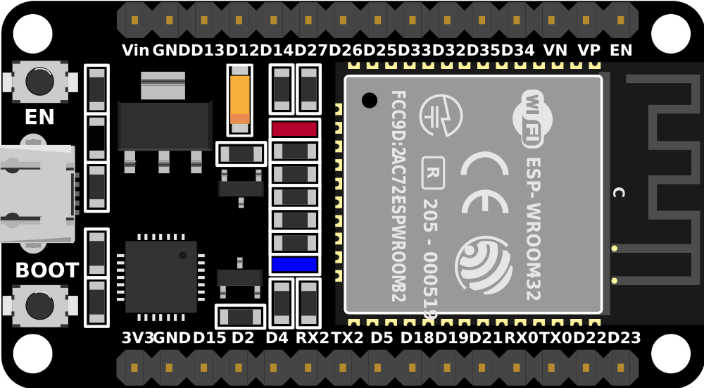
Pin Configuration and Descriptions
The ESP-WROOM32 module features 30 pins, each with specific functions. Below is the pinout description:
| Pin Number | Pin Name | Function |
|---|---|---|
| 1 | EN | Enable pin. Active high. Used to reset the module. |
| 2 | IO36 (VP) | ADC1 channel 0, GPIO36, input-only pin. |
| 3 | IO39 (VN) | ADC1 channel 3, GPIO39, input-only pin. |
| 4 | IO34 | ADC1 channel 6, GPIO34, input-only pin. |
| 5 | IO35 | ADC1 channel 7, GPIO35, input-only pin. |
| 6 | IO32 | ADC1 channel 4, GPIO32, touch sensor T9. |
| 7 | IO33 | ADC1 channel 5, GPIO33, touch sensor T8. |
| 8 | IO25 | DAC1, GPIO25, ADC2 channel 8. |
| 9 | IO26 | DAC2, GPIO26, ADC2 channel 9. |
| 10 | IO27 | GPIO27, ADC2 channel 7, touch sensor T7. |
| 11 | IO14 | GPIO14, ADC2 channel 6, touch sensor T6, HSPI CLK. |
| 12 | IO12 | GPIO12, ADC2 channel 5, touch sensor T5, HSPI MISO. |
| 13 | GND | Ground pin. |
| 14 | IO13 | GPIO13, ADC2 channel 4, touch sensor T4, HSPI MOSI. |
| 15 | IO9 | GPIO9, used for internal flash (not recommended for external use). |
| 16 | IO10 | GPIO10, used for internal flash (not recommended for external use). |
| 17 | IO23 | GPIO23, VSPI MOSI. |
| 18 | IO22 | GPIO22, I2C SCL. |
| 19 | IO1 (TX0) | UART0 TX pin, GPIO1. |
| 20 | IO3 (RX0) | UART0 RX pin, GPIO3. |
| 21 | IO21 | GPIO21, I2C SDA. |
| 22 | IO19 | GPIO19, VSPI MISO. |
| 23 | IO18 | GPIO18, VSPI CLK. |
| 24 | IO5 | GPIO5, VSPI CS0. |
| 25 | IO17 | GPIO17, UART2 TX. |
| 26 | IO16 | GPIO16, UART2 RX. |
| 27 | IO4 | GPIO4, ADC2 channel 0, touch sensor T0. |
| 28 | IO0 | GPIO0, ADC2 channel 1, touch sensor T1, boot mode selection. |
| 29 | IO2 | GPIO2, ADC2 channel 2, touch sensor T2. |
| 30 | 3V3 | 3.3V power supply input. |
Usage Instructions
The ESP-WROOM32 module is versatile and can be used in various circuits. Below are the steps and best practices for using it effectively:
How to Use the Component in a Circuit
- Power Supply: Connect the 3V3 pin to a 3.3V power source and GND to ground. Avoid exceeding the voltage range to prevent damage.
- Programming: Use a USB-to-serial adapter or development board (e.g., ESP32 DevKit) to program the module. The UART0 pins (TX0 and RX0) are used for communication.
- GPIO Usage: Configure GPIO pins as input, output, or alternate functions (e.g., ADC, PWM) in your code.
- Wi-Fi and Bluetooth: Use the ESP-IDF or Arduino IDE to configure wireless communication. Libraries like
WiFi.handBluetoothSerial.hsimplify development.
Important Considerations and Best Practices
- Voltage Levels: Ensure all GPIO pins operate at 3.3V logic levels. Use level shifters if interfacing with 5V devices.
- Boot Mode: Pull GPIO0 low during boot to enter programming mode.
- Antenna Placement: Avoid placing metal objects near the onboard antenna to ensure optimal wireless performance.
- Power Supply: Use a stable power source with sufficient current capacity (at least 500 mA) to avoid brownouts.
Example Code for Arduino UNO
Below is an example of how to connect and program the ESP-WROOM32 using the Arduino IDE:
#include <WiFi.h> // Include the Wi-Fi library

const char* ssid = "Your_SSID";       // Replace with your Wi-Fi network name
const char* password = "Your_Password"; // Replace with your Wi-Fi password

void setup() {
  Serial.begin(115200); // Initialize serial communication at 115200 baud
  WiFi.begin(ssid, password); // Connect to Wi-Fi network

  Serial.print("Connecting to Wi-Fi");
  while (WiFi.status() != WL_CONNECTED) {
    delay(500); // Wait for connection
    Serial.print(".");
  }
  Serial.println("\nConnected to Wi-Fi!");
  Serial.print("IP Address: ");
  Serial.println(WiFi.localIP()); // Print the module's IP address
}

void loop() {
  // Add your main code here
}
Troubleshooting and FAQs
Common Issues and Solutions
Module Not Responding:
- Ensure the EN pin is connected to 3.3V.
- Check the power supply for sufficient current.
Wi-Fi Connection Fails:
- Verify the SSID and password in your code.
- Check for interference or weak signal strength.
GPIO Pins Not Working:
- Confirm the pin mode is correctly set in your code.
- Avoid using reserved pins (e.g., IO9, IO10) for general purposes.
Programming Errors:
- Ensure GPIO0 is pulled low during programming.
- Use a reliable USB-to-serial adapter with proper drivers installed.
FAQs
Q: Can I use 5V logic with the ESP-WROOM32?
A: No, the module operates at 3.3V logic levels. Use level shifters for 5V devices.Q: How do I reduce power consumption?
A: Use deep sleep mode in your code to minimize power usage during idle periods.Q: Can I use the module without a development board?
A: Yes, but you will need external components like a USB-to-serial adapter and voltage regulator.
By following this documentation, you can effectively integrate the ESP-WROOM32 module into your projects and troubleshoot common issues.