How to Use DFROBOT ANALOG VOLTAGE DIVIDER V2: Examples, Pinouts, and Specs
Introduction
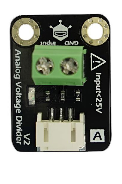
The DFROBOT Analog Voltage Divider V2 (Manufacturer Part ID: DFR0051) is a versatile module designed to scale down voltage levels, making them suitable for measurement by microcontrollers, sensors, or other low-voltage devices. This module features adjustable resistors, allowing for precise control over the output voltage. It is particularly useful in applications where high-voltage signals need to be safely interfaced with low-voltage systems.
Explore Projects Built with DFROBOT ANALOG VOLTAGE DIVIDER V2

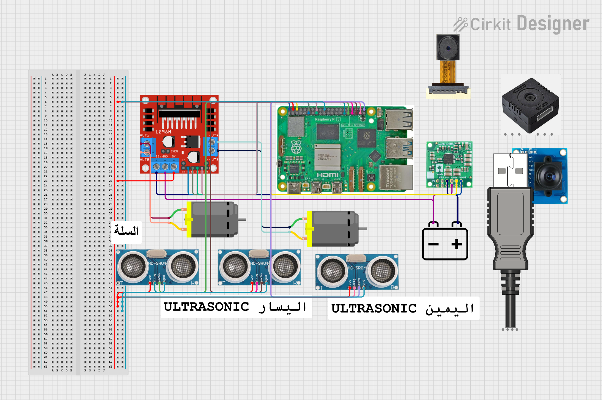
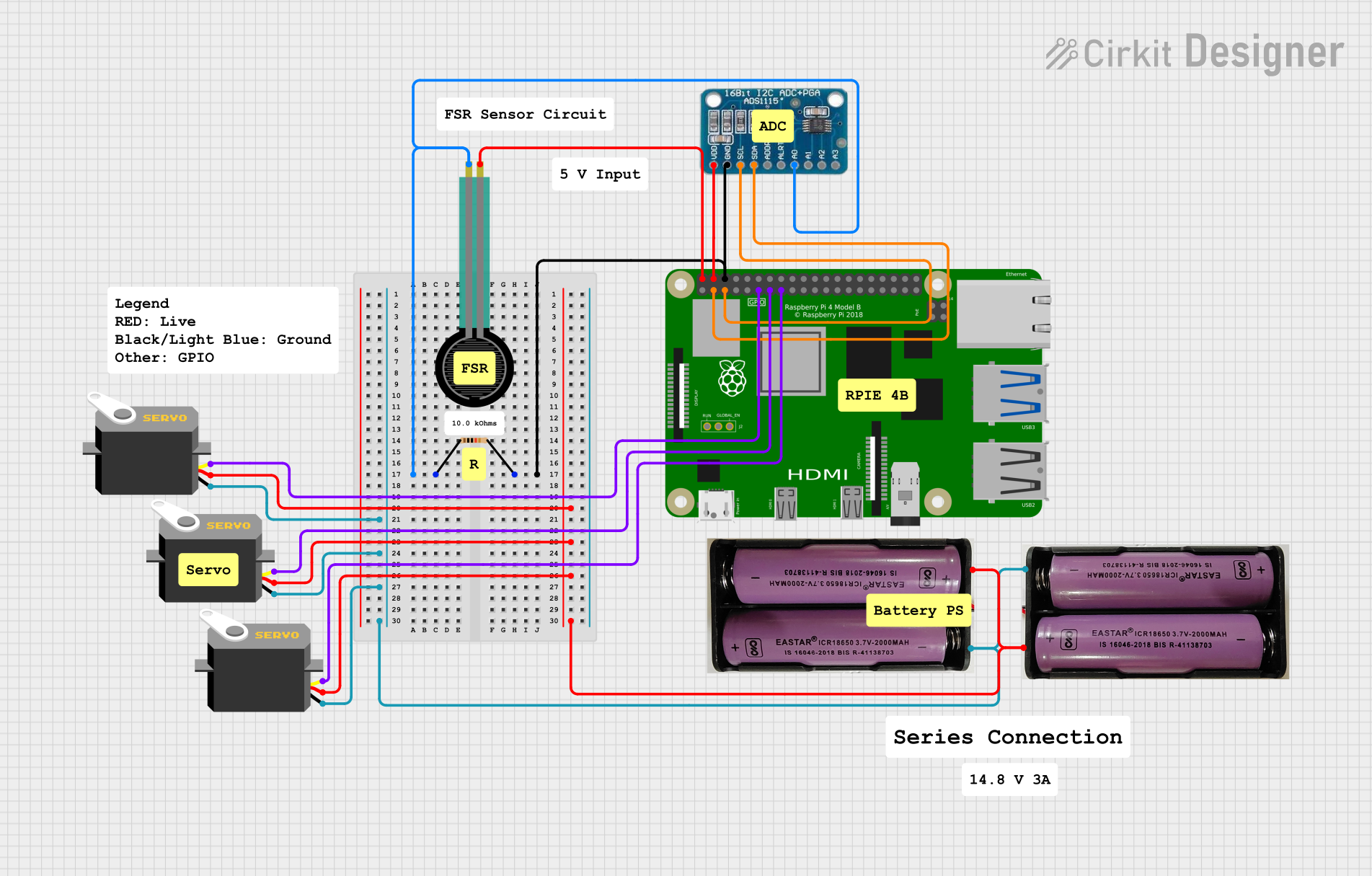
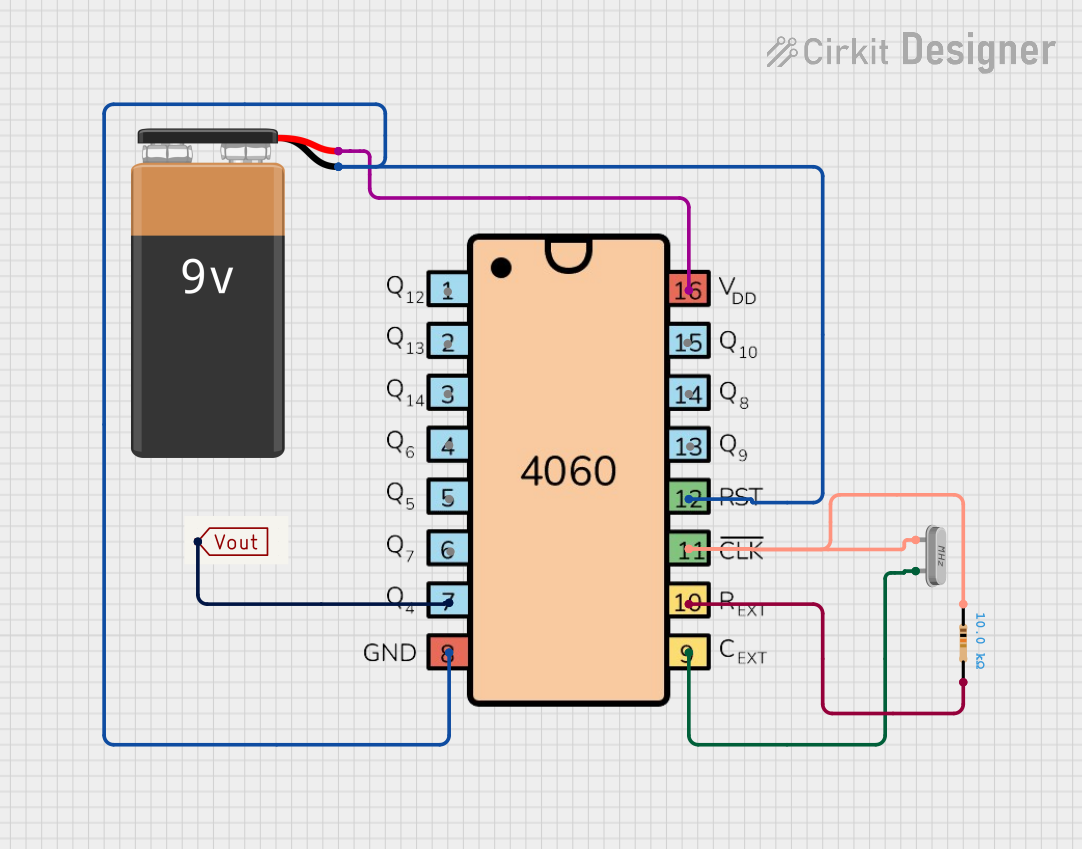
Explore Projects Built with DFROBOT ANALOG VOLTAGE DIVIDER V2
Common Applications and Use Cases
- Measuring battery voltage in robotics and IoT projects
- Scaling down high-voltage signals for microcontroller ADC inputs
- Monitoring power supply levels in embedded systems
- Voltage sensing in automotive or industrial applications
Technical Specifications
The following table outlines the key technical details of the DFROBOT Analog Voltage Divider V2:
| Parameter | Value |
|---|---|
| Input Voltage Range | 0–25V DC |
| Output Voltage Range | 0–5V DC (compatible with ADCs) |
| Voltage Divider Ratio | 5:1 |
| Accuracy | ±1% |
| Operating Temperature | -40°C to 85°C |
| Dimensions | 30mm x 22mm x 10mm |
| Weight | 5g |
Pin Configuration and Descriptions
The module has a simple pinout, as described in the table below:
| Pin | Label | Description |
|---|---|---|
| 1 | VCC |
Input voltage to be measured (0–25V DC) |
| 2 | GND |
Ground connection |
| 3 | OUT |
Scaled-down output voltage (0–5V DC) |
Usage Instructions
How to Use the Component in a Circuit
- Connect the Input Voltage: Attach the voltage source you want to measure to the
VCCpin. Ensure the input voltage does not exceed 25V DC. - Connect Ground: Connect the
GNDpin to the ground of your circuit. - Read the Output Voltage: The scaled-down voltage will be available at the
OUTpin. This output can be connected to an ADC pin of a microcontroller (e.g., Arduino UNO) for measurement.
Important Considerations and Best Practices
- Voltage Limits: Do not exceed the 25V input limit, as this may damage the module.
- Calibration: For precise measurements, calibrate the module by comparing the output voltage with a known reference voltage.
- Input Impedance: Ensure the input impedance of the connected ADC is high enough to avoid loading effects.
- Noise Reduction: Use decoupling capacitors if the input voltage is noisy.
Example: Using with Arduino UNO
Below is an example of how to use the DFROBOT Analog Voltage Divider V2 with an Arduino UNO to measure a voltage:
// Define the analog pin connected to the OUT pin of the voltage divider
const int voltagePin = A0;

// Define the voltage divider ratio (5:1)
const float dividerRatio = 5.0;

// Define the reference voltage of the Arduino (typically 5V)
const float referenceVoltage = 5.0;

void setup() {
  Serial.begin(9600); // Initialize serial communication at 9600 baud
}

void loop() {
  // Read the analog value from the voltage divider output
  int analogValue = analogRead(voltagePin);

  // Convert the analog value to a voltage
  float measuredVoltage = (analogValue / 1023.0) * referenceVoltage;

  // Scale up the voltage using the divider ratio
  float inputVoltage = measuredVoltage * dividerRatio;

  // Print the measured input voltage to the Serial Monitor
  Serial.print("Input Voltage: ");
  Serial.print(inputVoltage);
  Serial.println(" V");

  delay(1000); // Wait for 1 second before the next reading
}
Notes:
- Ensure the Arduino's ADC reference voltage matches the actual supply voltage (e.g., 5V or 3.3V).
- Use a multimeter to verify the input voltage for calibration purposes.
Troubleshooting and FAQs
Common Issues and Solutions
No Output Voltage:
- Ensure the input voltage is within the specified range (0–25V DC).
- Verify all connections, especially the
GNDpin.
Incorrect Voltage Readings:
- Check for loose or poor connections.
- Calibrate the module by comparing the output with a known reference voltage.
- Ensure the microcontroller's ADC reference voltage is correctly configured.
Output Voltage Exceeds 5V:
- Verify the input voltage does not exceed 25V.
- Check the voltage divider ratio and ensure the module is not damaged.
FAQs
Q: Can this module measure AC voltage?
A: No, the DFROBOT Analog Voltage Divider V2 is designed for DC voltage only. Measuring AC voltage may damage the module.
Q: Can I use this module with a 3.3V microcontroller?
A: Yes, but ensure the output voltage does not exceed the ADC input range of the microcontroller. Adjust the input voltage accordingly.
Q: How do I increase measurement accuracy?
A: Use a stable power supply, minimize noise in the input signal, and calibrate the module with a multimeter.
Q: Is the module protected against reverse polarity?
A: No, the module does not have reverse polarity protection. Ensure correct polarity when connecting the input voltage.
This concludes the documentation for the DFROBOT Analog Voltage Divider V2. For further assistance, refer to the official DFROBOT resources or contact their support team.