How to Use EEPROM: Examples, Pinouts, and Specs
Introduction
The R1EX24002ASAS0I is an EEPROM (Electrically Erasable Programmable Read-Only Memory) manufactured by Renesas. This non-volatile memory chip retains data even when power is turned off, making it ideal for applications requiring persistent data storage. The EEPROM can be electrically erased and reprogrammed, allowing for frequent updates to stored data without the need for external storage devices.
Explore Projects Built with EEPROM


Explore Projects Built with EEPROM
Common Applications and Use Cases
- Configuration data storage in embedded systems
- Calibration data storage for sensors
- Storing user preferences in consumer electronics
- Data logging in IoT devices
- Firmware updates and bootloader storage
Technical Specifications
The following table outlines the key technical details of the R1EX24002ASAS0I EEPROM:
| Parameter | Value |
|---|---|
| Memory Capacity | 2 Kbits (256 x 8 bits) |
| Operating Voltage Range | 1.8V to 5.5V |
| Maximum Clock Frequency | 1 MHz (at 5.0V) |
| Interface Type | I²C (2-wire serial interface) |
| Write Cycle Time | 5 ms (typical) |
| Data Retention | 100 years (at 25°C) |
| Endurance | 1,000,000 write/erase cycles |
| Operating Temperature | -40°C to +85°C |
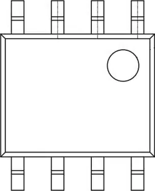
| Package Type | 8-pin SOP (Small Outline Package) |
Pin Configuration and Descriptions
The R1EX24002ASAS0I features an 8-pin configuration. The pinout and descriptions are as follows:
| Pin Number | Pin Name | Description |
|---|---|---|
| 1 | A0 | Address input bit 0 |
| 2 | A1 | Address input bit 1 |
| 3 | A2 | Address input bit 2 |
| 4 | VSS | Ground (0V) |
| 5 | SDA | Serial Data (I²C data line) |
| 6 | SCL | Serial Clock (I²C clock line) |
| 7 | WP | Write Protect (active high) |
| 8 | VCC | Power supply (1.8V to 5.5V) |
Usage Instructions
How to Use the Component in a Circuit
- Power Supply: Connect the VCC pin to a power source (1.8V to 5.5V) and the VSS pin to ground.
- I²C Interface: Connect the SDA and SCL pins to the corresponding I²C data and clock lines of your microcontroller. Use pull-up resistors (typically 4.7 kΩ) on both lines.
- Address Configuration: Use the A0, A1, and A2 pins to set the I²C address of the EEPROM. These pins can be connected to either VCC or VSS.
- Write Protection: If write protection is required, connect the WP pin to VCC. Otherwise, connect it to VSS or leave it floating.
Important Considerations and Best Practices
- Pull-Up Resistors: Ensure proper pull-up resistors are used on the SDA and SCL lines for reliable I²C communication.
- Write Cycles: Avoid excessive write operations to extend the lifespan of the EEPROM.
- Address Conflicts: If multiple I²C devices are used, ensure each device has a unique address by configuring the A0, A1, and A2 pins.
- Decoupling Capacitor: Place a 0.1 µF decoupling capacitor near the VCC pin to stabilize the power supply.
Example Code for Arduino UNO
Below is an example of how to interface the R1EX24002ASAS0I EEPROM with an Arduino UNO using the Wire library:
#include <Wire.h> // Include the Wire library for I²C communication

#define EEPROM_I2C_ADDRESS 0x50 // Base I²C address of the EEPROM

void setup() {
  Wire.begin(); // Initialize I²C communication
  Serial.begin(9600); // Initialize serial communication for debugging

  // Write a byte to EEPROM
  writeEEPROM(0x00, 0x42); // Write 0x42 to memory address 0x00
  delay(10); // Wait for the write cycle to complete

  // Read the byte back from EEPROM
  uint8_t data = readEEPROM(0x00);
  Serial.print("Read data: 0x");
  Serial.println(data, HEX); // Print the read data in hexadecimal format
}

void loop() {
  // Main loop does nothing
}

// Function to write a byte to the EEPROM
void writeEEPROM(uint8_t address, uint8_t data) {
  Wire.beginTransmission(EEPROM_I2C_ADDRESS);
  Wire.write(address); // Send memory address
  Wire.write(data);    // Send data byte
  Wire.endTransmission();
  delay(5); // Wait for the write cycle to complete
}

// Function to read a byte from the EEPROM
uint8_t readEEPROM(uint8_t address) {
  Wire.beginTransmission(EEPROM_I2C_ADDRESS);
  Wire.write(address); // Send memory address
  Wire.endTransmission();

  Wire.requestFrom(EEPROM_I2C_ADDRESS, 1); // Request 1 byte from EEPROM
  while (Wire.available() == 0); // Wait for data to become available
  return Wire.read(); // Read and return the data byte
}
Troubleshooting and FAQs
Common Issues and Solutions
EEPROM Not Responding on I²C Bus:
- Cause: Incorrect I²C address or wiring.
- Solution: Verify the A0, A1, and A2 pin configurations and ensure proper pull-up resistors are used on the SDA and SCL lines.
Data Corruption:
- Cause: Power loss during a write operation.
- Solution: Avoid power interruptions during write cycles and use a stable power supply.
Write Operations Failing:
- Cause: Write protection enabled.
- Solution: Ensure the WP pin is connected to VSS or left floating if write protection is not required.
Excessive Write Delays:
- Cause: Exceeding the maximum clock frequency or improper timing.
- Solution: Ensure the I²C clock frequency does not exceed 1 MHz and follow the recommended write cycle time.
FAQs
Q: Can I use this EEPROM with a 3.3V microcontroller?
A: Yes, the EEPROM operates within a voltage range of 1.8V to 5.5V, making it compatible with 3.3V systems.Q: How do I calculate the I²C address for the EEPROM?
A: The base address is 0x50. Modify the least significant bits based on the A0, A1, and A2 pin configurations.Q: What happens if I exceed the write endurance limit?
A: The EEPROM may fail to reliably store data after 1,000,000 write/erase cycles. Use wear-leveling techniques to extend its lifespan.