How to Use GPIO Extension Board: Examples, Pinouts, and Specs
Introduction
The GPIO Extension Board by Sunfounder (Part ID: Extension Board) is a versatile circuit board designed to expand the number of General Purpose Input/Output (GPIO) pins available for microcontrollers or single-board computers. This board simplifies the process of connecting multiple peripherals, sensors, and modules, making it an essential tool for prototyping and development in electronics projects.
Explore Projects Built with GPIO Extension Board


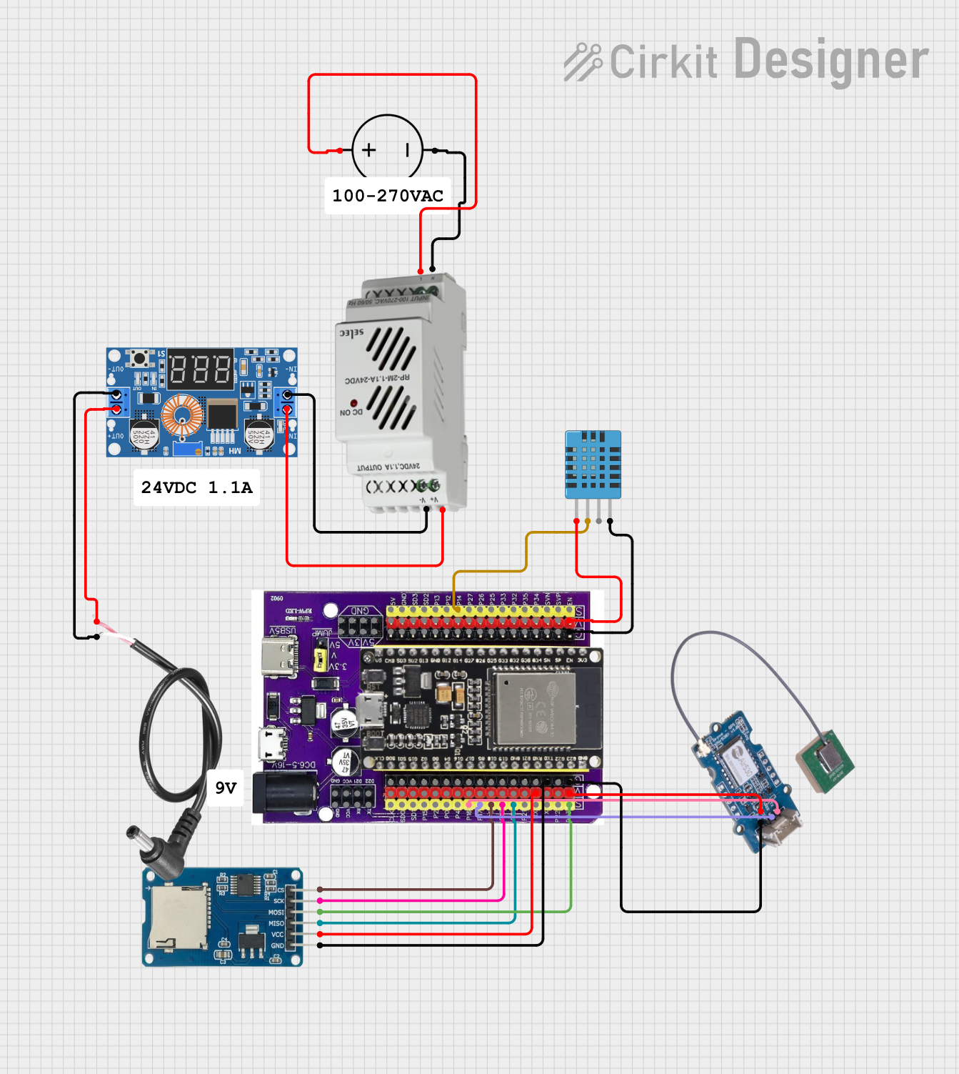
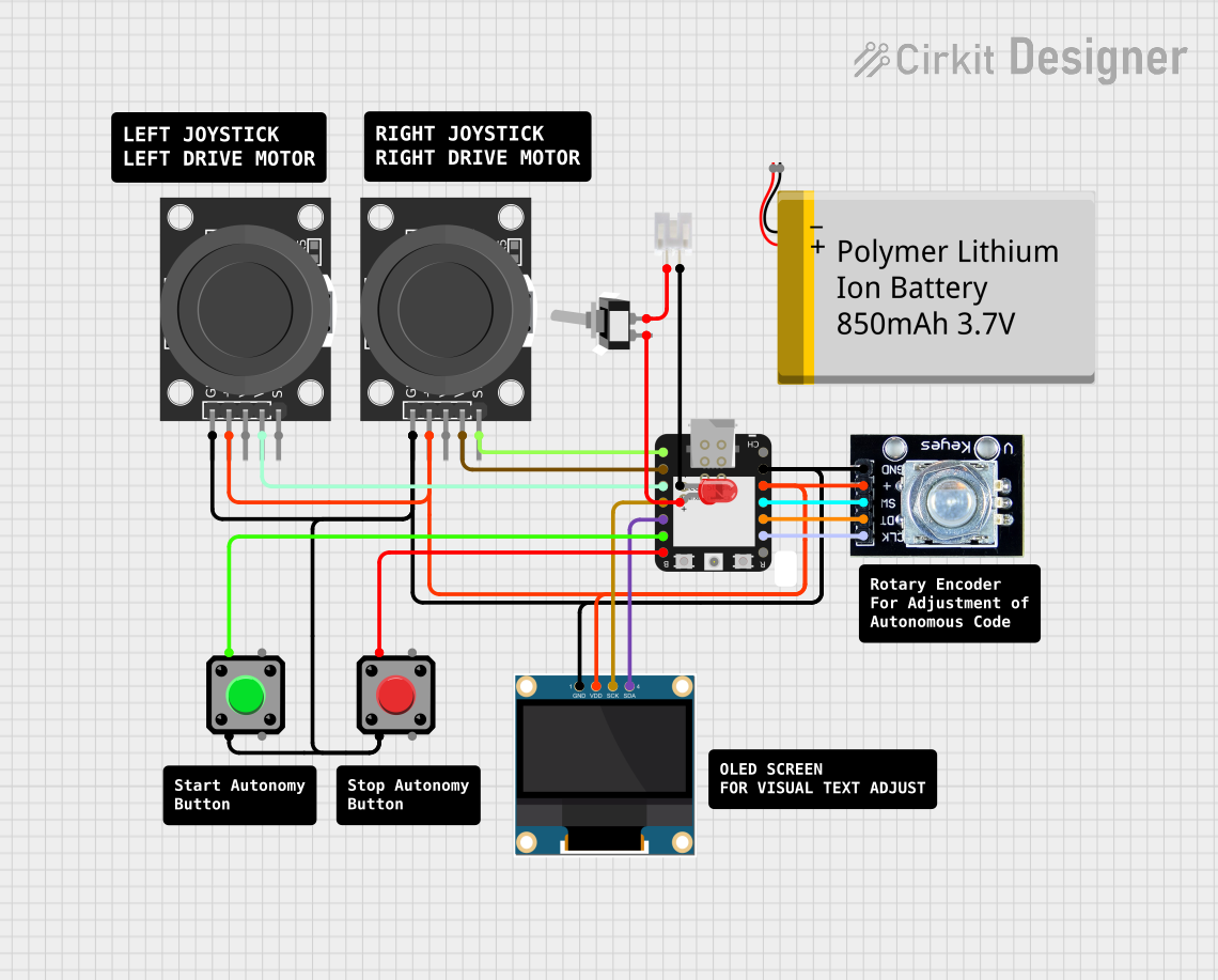
Explore Projects Built with GPIO Extension Board
Common Applications and Use Cases
- Expanding GPIO pin availability for microcontrollers like Arduino or Raspberry Pi.
- Simplifying connections for sensors, actuators, and other peripherals.
- Prototyping complex circuits with multiple input/output requirements.
- Educational projects and learning environments for electronics and programming.
Technical Specifications
The GPIO Extension Board is designed to be compatible with a wide range of microcontrollers and single-board computers. Below are the key technical details:
General Specifications
| Parameter | Value |
|---|---|
| Manufacturer | Sunfounder |
| Part ID | Extension Board |
| Input Voltage | 3.3V or 5V (depending on host) |
| GPIO Pin Compatibility | 40-pin GPIO header (Raspberry Pi) |
| Dimensions | 65mm x 56mm x 15mm |
| Operating Temperature | -40°C to 85°C |
Pin Configuration and Descriptions
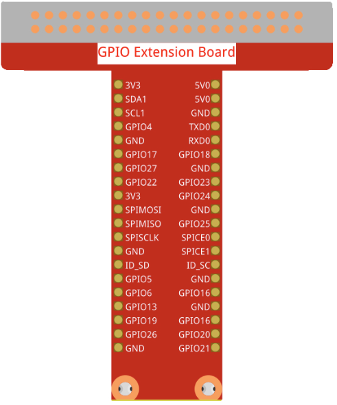
The GPIO Extension Board features a 40-pin GPIO header that maps directly to the GPIO pins of the host microcontroller or single-board computer. Below is the pinout description:
| Pin Number | Pin Name | Description |
|---|---|---|
| 1 | 3.3V | 3.3V power supply |
| 2 | 5V | 5V power supply |
| 3 | GPIO2 (SDA) | I2C Data Line |
| 4 | 5V | 5V power supply |
| 5 | GPIO3 (SCL) | I2C Clock Line |
| 6 | GND | Ground |
| ... | ... | ... (follows Raspberry Pi GPIO layout) |
| 39 | GND | Ground |
| 40 | GPIO21 | General Purpose I/O |
Note: The pinout follows the standard Raspberry Pi GPIO layout. For other microcontrollers, ensure compatibility before use.
Usage Instructions
How to Use the GPIO Extension Board in a Circuit
Connect the Board to the Host Device:
- Align the GPIO header of the extension board with the GPIO pins of your microcontroller or single-board computer.
- Gently press the board into place to ensure a secure connection.
Connect Peripherals:
- Use jumper wires to connect sensors, actuators, or other peripherals to the GPIO pins on the extension board.
- Refer to the pinout table to ensure correct connections.
Power the Board:
- The board draws power directly from the host device. Ensure the host device is powered on and capable of supplying sufficient current for all connected peripherals.
Program the Host Device:
- Write and upload code to the host microcontroller or single-board computer to control the connected peripherals.
Important Considerations and Best Practices
- Voltage Compatibility: Ensure that the connected peripherals operate at the same voltage level as the GPIO pins (3.3V or 5V).
- Avoid Overloading: Do not exceed the current rating of the GPIO pins to prevent damage to the host device.
- Secure Connections: Use proper connectors or soldering to ensure stable and reliable connections.
- Static Precautions: Handle the board with care to avoid static discharge, which can damage sensitive components.
Example: Using the GPIO Extension Board with Arduino UNO
Below is an example of how to use the GPIO Extension Board with an Arduino UNO to control an LED:
// Example: Blink an LED using the GPIO Extension Board
// Connect the LED's positive leg to GPIO pin 7 and the negative leg to GND.

const int ledPin = 7; // GPIO pin connected to the LED

void setup() {
  pinMode(ledPin, OUTPUT); // Set the GPIO pin as an output
}

void loop() {
  digitalWrite(ledPin, HIGH); // Turn the LED on
  delay(1000);                // Wait for 1 second
  digitalWrite(ledPin, LOW);  // Turn the LED off
  delay(1000);                // Wait for 1 second
}
Tip: Use resistors in series with LEDs to limit current and prevent damage.
Troubleshooting and FAQs
Common Issues and Solutions
Peripheral Not Responding:
- Cause: Incorrect GPIO pin connection or configuration.
- Solution: Double-check the pinout and ensure the correct pins are used in the code.
Board Not Powering On:
- Cause: Insufficient power supply from the host device.
- Solution: Verify that the host device is powered on and capable of supplying sufficient current.
Intermittent Connections:
- Cause: Loose or unstable connections.
- Solution: Ensure all connections are secure and use proper connectors or soldering.
Overheating:
- Cause: Excessive current draw from connected peripherals.
- Solution: Check the current requirements of all peripherals and ensure they do not exceed the GPIO pin ratings.
FAQs
Q1: Can the GPIO Extension Board be used with microcontrollers other than Raspberry Pi?
A1: Yes, the board can be used with other microcontrollers, but you must ensure the GPIO pinout and voltage levels are compatible.
Q2: How many peripherals can I connect to the board?
A2: The number of peripherals depends on the available GPIO pins and the power supply capacity of the host device.
Q3: Is the board compatible with 3.3V and 5V devices?
A3: Yes, the board supports both 3.3V and 5V devices, but ensure all connected peripherals operate at the same voltage level.
Q4: Do I need additional drivers to use the board?
A4: No, the GPIO Extension Board does not require additional drivers. It works as a passive extension of the host device's GPIO pins.