How to Use ESP32-P4-Eth: Examples, Pinouts, and Specs
Introduction
The ESP32-P4-Eth by WaveShare is a high-performance microcontroller designed for Internet of Things (IoT) applications. It combines integrated Wi-Fi and Bluetooth capabilities with an Ethernet interface, offering both wireless and wired connectivity options. This makes it ideal for projects requiring stable and reliable internet access. The ESP32-P4-Eth is widely recognized for its low power consumption, high processing speed, and ability to interface with a variety of sensors and peripherals.
Explore Projects Built with ESP32-P4-Eth


Explore Projects Built with ESP32-P4-Eth
Common Applications and Use Cases
- Smart home automation systems
- Industrial IoT applications
- Data logging and monitoring systems
- Networked sensor hubs
- Robotics and automation
- Projects requiring hybrid (wired and wireless) connectivity
Technical Specifications
Key Technical Details
| Parameter | Specification |
|---|---|
| Microcontroller | ESP32-P4 |
| Wireless Connectivity | Wi-Fi 802.11 b/g/n, Bluetooth 5.0 |
| Wired Connectivity | Ethernet (10/100 Mbps) |
| Operating Voltage | 3.3V |
| Input Voltage Range | 5V (via USB) or 7-12V (via VIN pin) |
| Flash Memory | 4MB |
| SRAM | 512KB |
| GPIO Pins | 34 |
| Communication Interfaces | UART, SPI, I2C, I2S, CAN, PWM |
| Power Consumption | Ultra-low power mode supported |
| Dimensions | 58mm x 25mm |
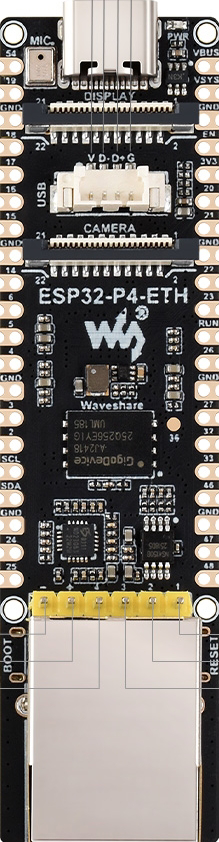
Pin Configuration and Descriptions
The ESP32-P4-Eth features a variety of pins for interfacing with external devices. Below is the pinout description:
| Pin Name | Type | Description |
|---|---|---|
| VIN | Power | Input voltage (7-12V) for powering the board |
| 3V3 | Power | 3.3V output for powering external components |
| GND | Ground | Ground connection |
| GPIO0 | GPIO | General-purpose I/O pin, often used for boot mode selection |
| GPIO1 | UART TX | UART transmit pin |
| GPIO3 | UART RX | UART receive pin |
| GPIO12 | GPIO | General-purpose I/O pin |
| GPIO13 | GPIO | General-purpose I/O pin |
| GPIO14 | GPIO | General-purpose I/O pin |
| GPIO15 | GPIO | General-purpose I/O pin |
| EN | Enable | Enable pin to reset the microcontroller |
| ETH_TXD0 | Ethernet | Ethernet transmit data pin 0 |
| ETH_TXD1 | Ethernet | Ethernet transmit data pin 1 |
| ETH_RXD0 | Ethernet | Ethernet receive data pin 0 |
| ETH_RXD1 | Ethernet | Ethernet receive data pin 1 |
| ETH_CLK | Ethernet | Ethernet clock signal |
Usage Instructions
How to Use the ESP32-P4-Eth in a Circuit
Powering the Board:
- Use the VIN pin to supply 7-12V, or connect a 5V USB power source.
- Ensure the power supply is stable to avoid damage to the board.
Connecting to Ethernet:
- Connect the Ethernet cable to the RJ45 port on the board.
- Use the Ethernet pins (e.g., ETH_TXD0, ETH_RXD0) for custom Ethernet interfacing if needed.
Programming the Board:
- Use the USB interface to connect the ESP32-P4-Eth to your computer.
- Install the necessary drivers and use the Arduino IDE or ESP-IDF for programming.
Interfacing with Sensors and Devices:
- Use the GPIO pins for connecting sensors, actuators, or other peripherals.
- Configure the pins in your code as input or output based on your application.
Important Considerations and Best Practices
- Voltage Levels: Ensure all connected devices operate at 3.3V logic levels to avoid damaging the board.
- Ethernet Usage: For stable Ethernet connectivity, use high-quality cables and ensure proper grounding.
- Wi-Fi and Bluetooth: Avoid placing the board in areas with significant RF interference to maintain wireless performance.
- Heat Management: If the board is used in high-performance applications, consider adding a heat sink to manage heat dissipation.
Example Code for Arduino IDE
Below is an example of how to use the ESP32-P4-Eth to connect to a Wi-Fi network and send data over Ethernet:
#include <WiFi.h>
#include <ETH.h>

// Wi-Fi credentials
const char* ssid = "Your_SSID";
const char* password = "Your_PASSWORD";

// Ethernet configuration
#define ETH_CLK_MODE ETH_CLOCK_GPIO17_OUT // Set Ethernet clock mode
#define ETH_PHY_POWER 12                  // GPIO pin for Ethernet PHY power

void setup() {
  Serial.begin(115200);

  // Initialize Wi-Fi
  WiFi.begin(ssid, password);
  Serial.print("Connecting to Wi-Fi");
  while (WiFi.status() != WL_CONNECTED) {
    delay(500);
    Serial.print(".");
  }
  Serial.println("\nWi-Fi connected!");

  // Initialize Ethernet
  ETH.begin(ETH_PHY_ADDR, ETH_PHY_POWER, ETH_CLK_MODE, ETH_PHY_MDC, ETH_PHY_MDIO);
  Serial.println("Ethernet initialized!");
}

void loop() {
  // Print IP addresses
  Serial.print("Wi-Fi IP: ");
  Serial.println(WiFi.localIP());
  Serial.print("Ethernet IP: ");
  Serial.println(ETH.localIP());

  delay(5000); // Wait 5 seconds before printing again
}
Troubleshooting and FAQs
Common Issues and Solutions
The board does not power on:
- Ensure the power supply voltage is within the specified range (7-12V for VIN or 5V via USB).
- Check the connections and ensure the power source is functional.
Wi-Fi connection fails:
- Verify the SSID and password in your code.
- Check for RF interference or weak signal strength.
- Restart the board and try reconnecting.
Ethernet does not work:
- Ensure the Ethernet cable is securely connected.
- Verify the Ethernet pins are correctly configured in your code.
- Check the network settings and ensure the router is functional.
GPIO pins not responding:
- Confirm the pins are correctly configured as input or output in your code.
- Check for short circuits or incorrect wiring.
FAQs
Q: Can I use the ESP32-P4-Eth with the Arduino IDE?
A: Yes, the ESP32-P4-Eth is fully compatible with the Arduino IDE. Install the ESP32 board package to get started.
Q: Does the board support PoE (Power over Ethernet)?
A: No, the ESP32-P4-Eth does not support PoE. You must provide power via VIN or USB.
Q: How do I reset the board?
A: Press the EN (Enable) button on the board to reset the microcontroller.
Q: Can I use both Wi-Fi and Ethernet simultaneously?
A: Yes, the ESP32-P4-Eth supports simultaneous use of Wi-Fi and Ethernet for hybrid connectivity.