How to Use esp32 r1 d32: Examples, Pinouts, and Specs
Introduction
The ESP32 R1 D32, manufactured by Burhan Butt, is a powerful and versatile microcontroller module designed for IoT (Internet of Things) applications. It features dual-core processing, integrated Wi-Fi, and Bluetooth capabilities, making it ideal for a wide range of wireless communication and control tasks. The ESP32 R1 D32 is widely used in smart home devices, wearable electronics, industrial automation, and other embedded systems requiring connectivity and low power consumption.
Explore Projects Built with esp32 r1 d32

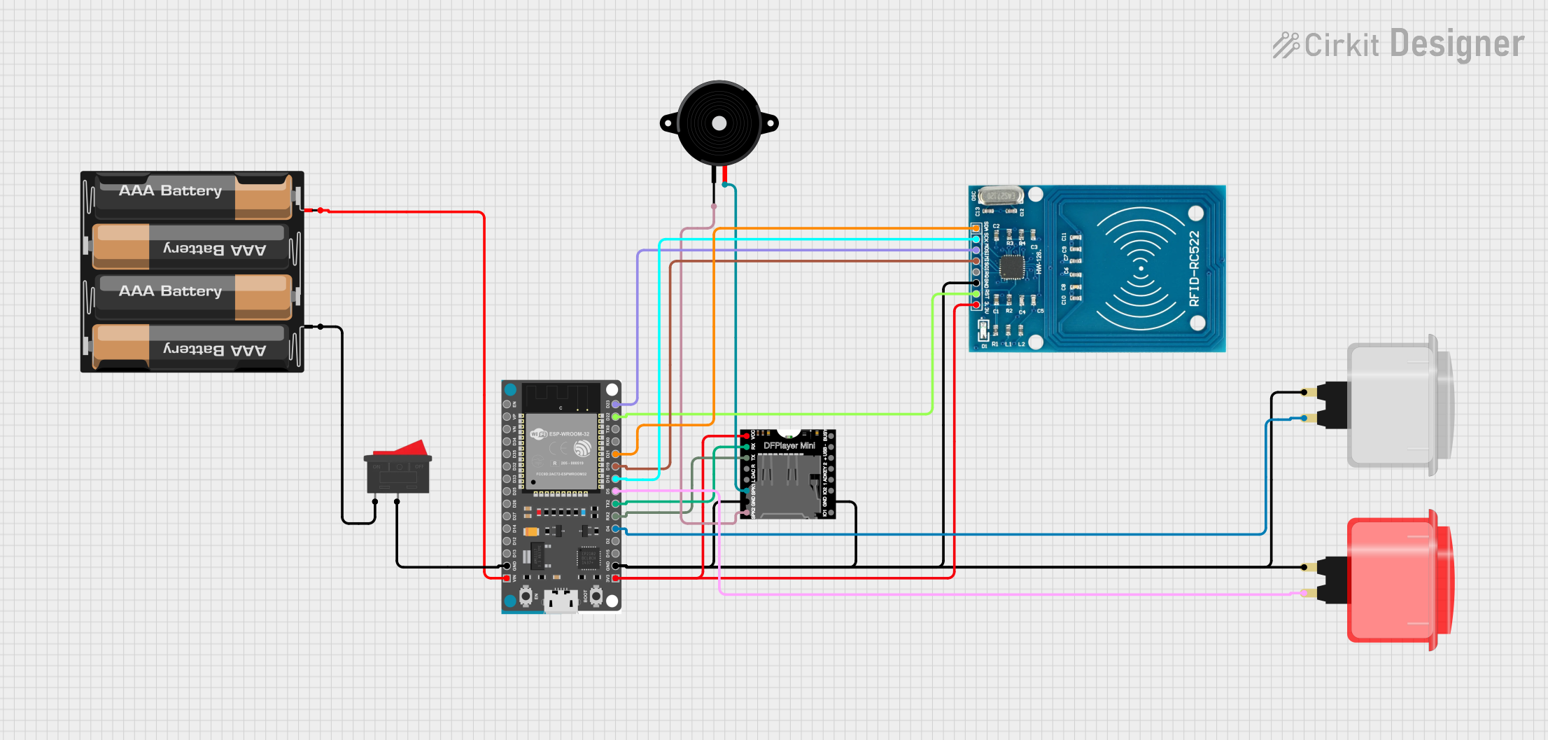

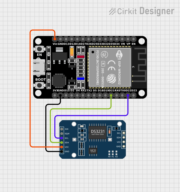
Explore Projects Built with esp32 r1 d32
Technical Specifications
- Manufacturer: Burhan Butt
- Part ID: ESP32 R1 D32
- Processor: Dual-core Xtensa® 32-bit LX6 microprocessor
- Clock Speed: Up to 240 MHz
- Flash Memory: 4 MB
- SRAM: 520 KB
- Connectivity: Wi-Fi 802.11 b/g/n, Bluetooth v4.2 BR/EDR and BLE
- Operating Voltage: 3.3V
- Input Voltage Range: 5V (via USB) or 3.3V (via VIN pin)
- GPIO Pins: 34 (including ADC, DAC, PWM, I2C, SPI, UART)
- ADC Resolution: 12-bit
- DAC Resolution: 8-bit
- Power Consumption: Ultra-low power consumption in deep sleep mode (~10 µA)
- Dimensions: 25.4 mm x 50.8 mm
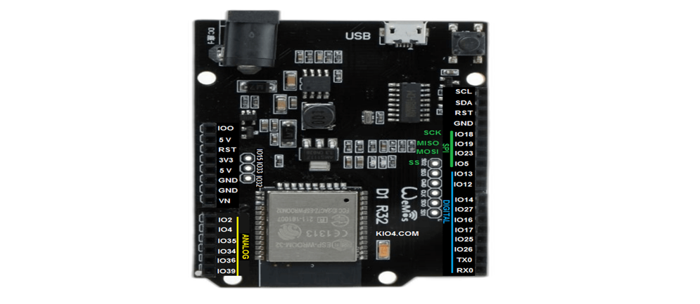
Pin Configuration and Descriptions
The ESP32 R1 D32 has a total of 38 pins. Below is a summary of the key pins and their functions:
| Pin Name | Type | Description |
|---|---|---|
| VIN | Power Input | Input voltage (5V) for powering the module via an external power source. |
| 3V3 | Power Output | Regulated 3.3V output for powering external components. |
| GND | Ground | Ground connection. |
| EN | Enable | Enables or disables the module. Active high. |
| GPIO0 | Digital I/O | General-purpose I/O pin. Used for boot mode selection during programming. |
| GPIO2 | Digital I/O | General-purpose I/O pin. |
| GPIO12-15 | Digital I/O | General-purpose I/O pins with additional ADC/DAC functionality. |
| TXD0, RXD0 | UART | UART0 transmit (TX) and receive (RX) pins for serial communication. |
| SCL, SDA | I2C | I2C clock (SCL) and data (SDA) pins for communication with I2C devices. |
| MOSI, MISO | SPI | SPI data pins for communication with SPI devices. |
| A0-A5 | Analog Input | ADC pins for reading analog signals (0-3.3V). |
| DAC1, DAC2 | Analog Output | DAC pins for generating analog output signals. |
| BOOT | Boot Mode | Used to enter bootloader mode for programming. |
Usage Instructions
How to Use the ESP32 R1 D32 in a Circuit
Powering the Module:
- Connect a 5V power source to the VIN pin or use a USB cable to power the module.
- Ensure the GND pin is connected to the ground of your circuit.
Programming the Module:
- Use the Arduino IDE or ESP-IDF (Espressif IoT Development Framework) to program the ESP32 R1 D32.
- Connect the module to your computer via a USB cable.
- Select the correct board ("ESP32 Dev Module") and port in the Arduino IDE.
Connecting Peripherals:
- Use the GPIO pins to connect sensors, actuators, or other peripherals.
- For analog sensors, connect them to the ADC pins (A0-A5).
- For communication with I2C or SPI devices, use the respective pins (SCL/SDA or MOSI/MISO).
Uploading Code:
- Write your code in the Arduino IDE and click the "Upload" button.
- Press and hold the BOOT button on the module if required during the upload process.
Example Code: Blinking an LED
The following example demonstrates how to blink an LED connected to GPIO2:
// Define the GPIO pin where the LED is connected
const int ledPin = 2;

void setup() {
  // Set the LED pin as an output
  pinMode(ledPin, OUTPUT);
}

void loop() {
  // Turn the LED on
  digitalWrite(ledPin, HIGH);
  delay(1000); // Wait for 1 second

  // Turn the LED off
  digitalWrite(ledPin, LOW);
  delay(1000); // Wait for 1 second
}
Important Considerations and Best Practices
- Always use a level shifter when interfacing the ESP32 R1 D32 with 5V logic devices, as the module operates at 3.3V logic levels.
- Avoid exceeding the maximum current rating of the GPIO pins (12 mA per pin).
- Use proper decoupling capacitors near the power pins to ensure stable operation.
- When using Wi-Fi or Bluetooth, ensure a strong and stable power supply to avoid brownout issues.
Troubleshooting and FAQs
Common Issues and Solutions
Issue: The module is not detected by the computer.
Solution:- Ensure the USB cable is functional and supports data transfer.
- Install the correct USB-to-serial driver for the ESP32 R1 D32.
Issue: Code upload fails with a timeout error.
Solution:- Press and hold the BOOT button while uploading the code.
- Check the selected board and port in the Arduino IDE.
Issue: The module resets unexpectedly during operation.
Solution:- Verify that the power supply is stable and capable of providing sufficient current.
- Add a capacitor (e.g., 100 µF) across the VIN and GND pins to filter power fluctuations.
Issue: Wi-Fi connection is unstable.
Solution:- Ensure the module is within range of the Wi-Fi router.
- Reduce interference by moving the module away from other electronic devices.
FAQs
Q: Can the ESP32 R1 D32 be powered directly from a 3.7V LiPo battery?
A: Yes, connect the battery to the VIN pin. However, ensure the battery voltage does not exceed 5V.Q: How many devices can be connected via Bluetooth?
A: The ESP32 R1 D32 supports up to 7 simultaneous Bluetooth connections.Q: Can I use the ESP32 R1 D32 for audio applications?
A: Yes, the module supports I2S for audio input/output and has built-in DACs for audio signal generation.
This documentation provides a comprehensive guide to using the ESP32 R1 D32 effectively in your projects. For further assistance, refer to the official datasheet or community forums.