How to Use DHT 11 : Examples, Pinouts, and Specs
Introduction
The DHT11 is a widely used digital temperature and humidity sensor that offers a simple interface and easy integration into various electronic projects, including DIY projects and home automation systems. It measures the surrounding air and provides a digital signal with the temperature and humidity readings. Its cost-effectiveness and simplicity make it an ideal choice for hobbyists and educators who are introducing concepts of environmental sensing.
Explore Projects Built with DHT 11
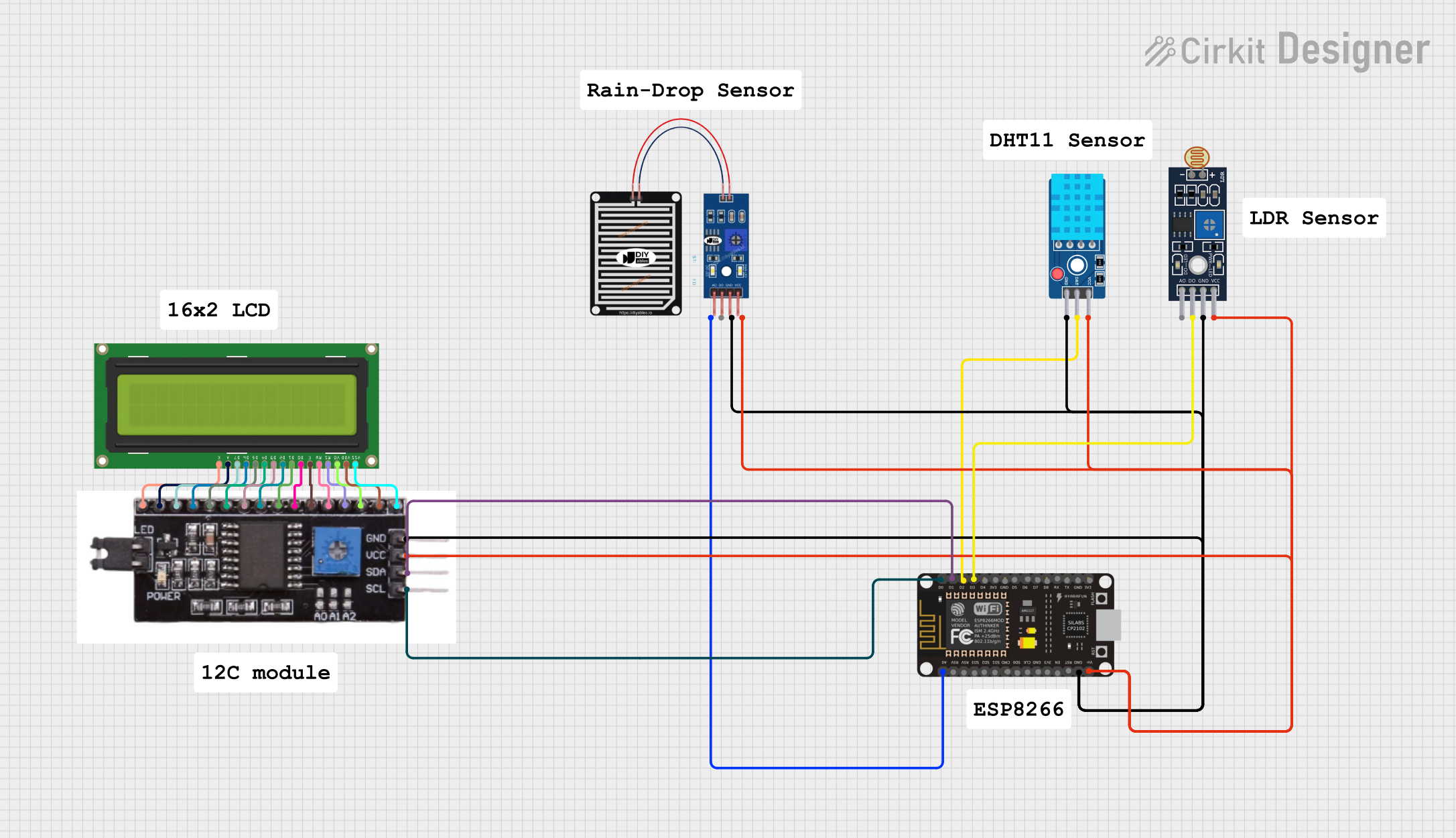
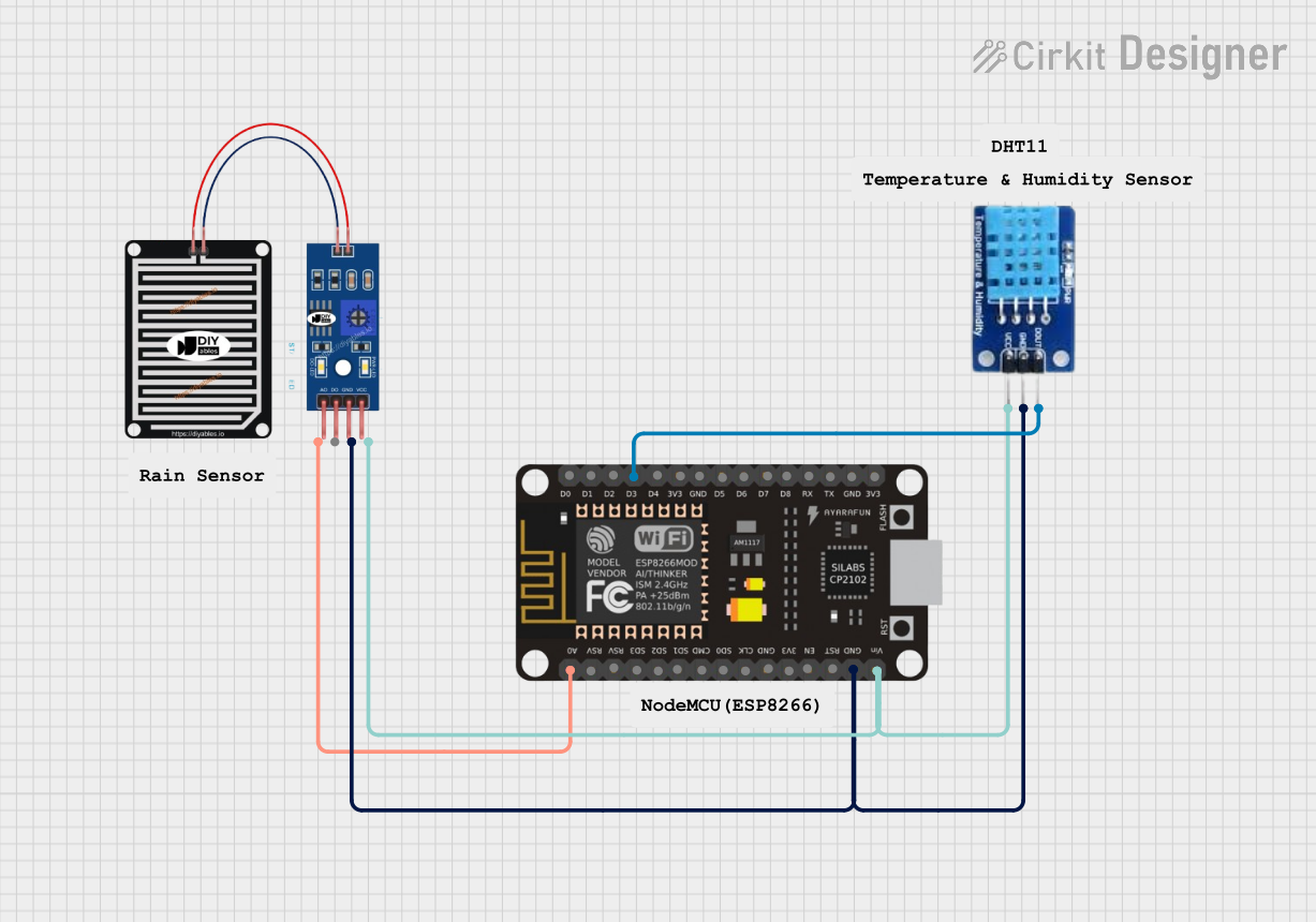
Explore Projects Built with DHT 11
Common Applications and Use Cases
- Home weather stations
- Environmental monitoring
- HVAC systems
- Incubators
- Consumer electronics
Technical Specifications
Key Technical Details
- Supply Voltage: 3.5 to 5.5 V DC
- Output Signal: Digital signal via a single data pin
- Humidity Measurement Range: 20 to 80% RH
- Humidity Accuracy: ±5% RH
- Temperature Measurement Range: 0 to 50°C
- Temperature Accuracy: ±2°C
- Resolution: 1% RH for humidity, 1°C for temperature
- Sampling Rate: No more than 1 Hz (once every second)
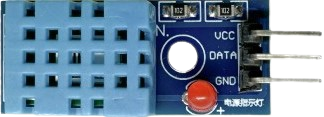
Pin Configuration and Descriptions
| Pin Number | Name | Description |
|---|---|---|
| 1 | VCC | Power supply (3.5-5.5 V DC) |
| 2 | DATA | Digital data output |
| 3 | NC | Not connected |
| 4 | GND | Ground |
Usage Instructions
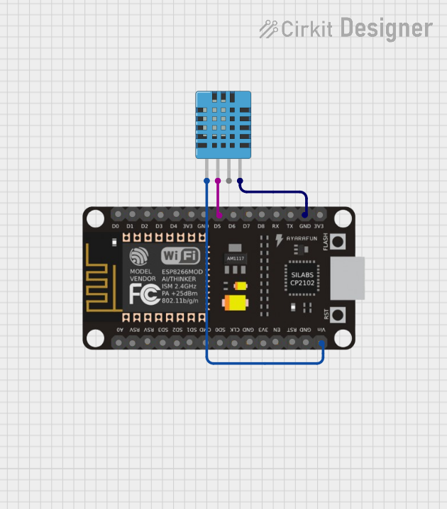
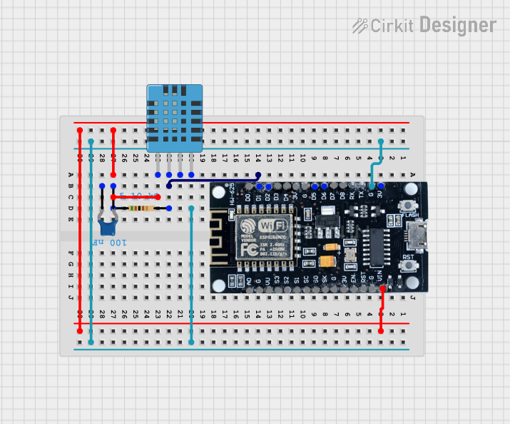
Integration with a Circuit
- Connect the VCC pin to a 3.5-5.5 V power supply.
- Connect the GND pin to the ground of the power supply.
- Connect the DATA pin to a digital input pin on your microcontroller, such as an Arduino UNO.
Important Considerations and Best Practices
- Ensure that the power supply is stable and within the specified voltage range.
- Place the sensor in an environment with good air circulation to get accurate readings.
- Avoid placing the sensor near heat sources or in direct sunlight.
- Allow the sensor to acclimatize to the environment for accurate readings.
- Use a pull-up resistor (typically 4.7kΩ to 10kΩ) on the DATA pin when connecting to a microcontroller.
Example Code for Arduino UNO
#include "DHT.h"

#define DHTPIN 2     // Digital pin connected to the DHT sensor
#define DHTTYPE DHT11 // DHT 11

DHT dht(DHTPIN, DHTTYPE);

void setup() {
  Serial.begin(9600);
  dht.begin();
}

void loop() {
  // Wait a few seconds between measurements.
  delay(2000);

  // Reading temperature or humidity takes about 250 milliseconds!
  float humidity = dht.readHumidity();
  float temperature = dht.readTemperature();

  // Check if any reads failed and exit early (to try again).
  if (isnan(humidity) || isnan(temperature)) {
    Serial.println("Failed to read from DHT sensor!");
    return;
  }

  // Compute heat index in Celsius (isFahrenheit = false)
  float heat_index = dht.computeHeatIndex(temperature, humidity, false);

  Serial.print("Humidity: ");
  Serial.print(humidity);
  Serial.print("%  Temperature: ");
  Serial.print(temperature);
  Serial.print("°C  Heat index: ");
  Serial.print(heat_index);
  Serial.println("°C");
}
Troubleshooting and FAQs
Common Issues
- Inaccurate Readings: Ensure the sensor is not placed near heat sources or in direct sunlight. Allow it to acclimatize to the environment.
- No Data: Check the wiring, especially the DATA pin connection. Ensure the pull-up resistor is in place.
- Erratic Readings: Ensure the power supply is stable and within the recommended voltage range.
Solutions and Tips for Troubleshooting
- Sensor Not Responding: Reset the power to the sensor and check the connections.
- Consistently High or Low Readings: Calibrate the sensor in a known environment or compare it with another sensor.
- Intermittent Readings: Reduce the length of the wires if possible, and ensure there is no electromagnetic interference.
FAQs
Q: How long does the DHT11 need to acclimatize to the environment? A: It is recommended to let the DHT11 sensor sit in the new environment for at least an hour before taking readings.
Q: Can the DHT11 sensor be used outdoors? A: The DHT11 is not waterproof and is designed for indoor use. If used outdoors, it should be placed in a protective enclosure.
Q: How often can I read data from the DHT11? A: The DHT11 should not be read more than once every second. Reading it more frequently may lead to self-heating and inaccurate readings.