
How to Use CC1101: Examples, Pinouts, and Specs
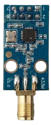
 Design with CC1101 in Cirkit Designer
Introduction
The CC1101 is a low-power sub-1 GHz transceiver designed for wireless communication in the ISM (Industrial, Scientific, and Medical) and SRD (Short-Range Device) frequency bands. Manufactured by Fart, this component is highly versatile and supports multiple modulation formats, including ASK, FSK, GFSK, and MSK. Its low power consumption and robust performance make it ideal for applications such as remote controls, wireless sensor networks, home automation, and industrial monitoring systems.
Explore Projects Built with CC1101
 Open Project in Cirkit Designer
 Open Project in Cirkit Designer
 Open Project in Cirkit Designer
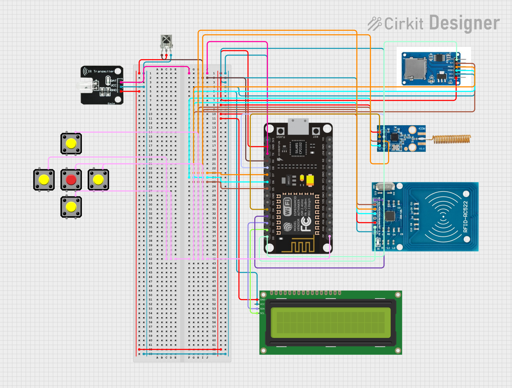 Open Project in Cirkit Designer
Explore Projects Built with CC1101
Open Project in Cirkit DesignerOpen Project in Cirkit DesignerOpen Project in Cirkit DesignerOpen Project in Cirkit DesignerCommon Applications
- Remote control systems (e.g., garage doors, drones)
- Wireless sensor networks
- Home automation (e.g., smart lighting, thermostats)
- Industrial monitoring and control
- Low-power telemetry systems
Technical Specifications
The CC1101 is a feature-rich transceiver with the following key specifications:
| Parameter | Value |
|---|---|
| Frequency Range | 300 MHz to 928 MHz (programmable) |
| Modulation Formats | ASK, FSK, GFSK, MSK |
| Data Rate | 0.6 kbps to 600 kbps |
| Supply Voltage | 1.8 V to 3.6 V |
| Current Consumption | 14.7 mA (RX mode at 433 MHz), 12.7 mA (TX mode at 10 dBm, 433 MHz) |
| Output Power | Programmable up to +12 dBm |
| Sensitivity | -116 dBm at 1.2 kbps, -112 dBm at 38.4 kbps |
| Operating Temperature Range | -40°C to +85°C |
| Interface | SPI (Serial Peripheral Interface) |
Pin Configuration and Descriptions
The CC1101 comes in a 20-pin QFN package. Below is the pin configuration:
| Pin Number | Pin Name | Description |
|---|---|---|
| 1 | GND | Ground connection |
| 2 | GND | Ground connection |
| 3 | GDO2 | General-purpose digital output pin 2 |
| 4 | GDO0 | General-purpose digital output pin 0 |
| 5 | GND | Ground connection |
| 6 | SI | SPI data input |
| 7 | SO | SPI data output |
| 8 | SCLK | SPI clock input |
| 9 | CSn | SPI chip select (active low) |
| 10 | GND | Ground connection |
| 11 | AVDD | Analog supply voltage |
| 12 | DVDD | Digital supply voltage |
| 13 | XOSC_Q1 | Crystal oscillator input |
| 14 | XOSC_Q2 | Crystal oscillator output |
| 15 | RF_P | RF positive signal |
| 16 | RF_N | RF negative signal |
| 17 | GND | Ground connection |
| 18 | TEST_EN | Test enable (used for factory testing, leave unconnected in normal operation) |
| 19 | RESET_N | Reset pin (active low) |
| 20 | GND | Ground connection |
Usage Instructions
How to Use the CC1101 in a Circuit
- Power Supply: Connect the CC1101 to a stable power source within the range of 1.8 V to 3.6 V. Ensure proper decoupling capacitors are placed near the power pins (AVDD and DVDD) to reduce noise.
- SPI Communication: Interface the CC1101 with a microcontroller using the SPI protocol. Connect the
SI,SO,SCLK, andCSnpins to the corresponding SPI pins on the microcontroller. - Antenna Connection: Attach an appropriate antenna to the
RF_PandRF_Npins for optimal wireless performance. Use a matching network if necessary. - Crystal Oscillator: Connect a 26 MHz crystal oscillator to the
XOSC_Q1andXOSC_Q2pins. Use appropriate load capacitors as specified in the datasheet. - Configuration: Program the CC1101 registers via SPI to set the desired frequency, modulation format, data rate, and other parameters. Refer to the datasheet for detailed register settings.
Important Considerations
- Grounding: Ensure all ground pins are properly connected to a common ground plane to minimize noise and interference.
- Antenna Design: Use a well-designed antenna and matching network to achieve optimal range and performance.
- Power Management: Utilize the low-power modes of the CC1101 to extend battery life in portable applications.
- Reset: Use the
RESET_Npin to reset the device if it becomes unresponsive.
Example Code for Arduino UNO
Below is an example of how to interface the CC1101 with an Arduino UNO using the SPI library:
#include <SPI.h>

// Define CC1101 pins
#define CC1101_CS 10  // Chip select pin
#define CC1101_GDO0 2 // GDO0 pin for interrupt handling

void setup() {
  // Initialize SPI
  SPI.begin();
  pinMode(CC1101_CS, OUTPUT);
  digitalWrite(CC1101_CS, HIGH); // Set CS high to deselect CC1101

  pinMode(CC1101_GDO0, INPUT); // Set GDO0 as input

  Serial.begin(9600);
  Serial.println("Initializing CC1101...");

  // Reset CC1101
  resetCC1101();

  // Example: Write to a CC1101 register (e.g., setting frequency)
  writeCC1101Register(0x0D, 0x21); // Example register and value
}

void loop() {
  // Main loop code
}

// Function to reset CC1101
void resetCC1101() {
  digitalWrite(CC1101_CS, LOW);
  delay(1);
  digitalWrite(CC1101_CS, HIGH);
  delay(1);
  digitalWrite(CC1101_CS, LOW);
  delay(1);
  digitalWrite(CC1101_CS, HIGH);
  delay(1);
}

// Function to write to a CC1101 register
void writeCC1101Register(byte addr, byte value) {
  digitalWrite(CC1101_CS, LOW); // Select CC1101
  SPI.transfer(addr);           // Send register address
  SPI.transfer(value);          // Send value
  digitalWrite(CC1101_CS, HIGH); // Deselect CC1101
}
Troubleshooting and FAQs
Common Issues
No Communication with CC1101:
- Ensure the SPI connections are correct and the
CSnpin is properly toggled. - Verify that the microcontroller and CC1101 are operating at compatible voltage levels.
- Ensure the SPI connections are correct and the
Poor Wireless Range:
- Check the antenna design and placement. Ensure there are no obstructions or interference sources nearby.
- Verify that the RF output power is configured correctly in the CC1101 registers.
Device Not Responding:
- Use the
RESET_Npin to reset the CC1101. - Check the power supply and ensure proper decoupling capacitors are in place.
- Use the
FAQs
Q: Can the CC1101 operate at 2.4 GHz?
A: No, the CC1101 is designed for sub-1 GHz frequencies (300 MHz to 928 MHz). For 2.4 GHz applications, consider using a different transceiver such as the CC2500.
Q: What is the maximum data rate supported by the CC1101?
A: The CC1101 supports data rates up to 600 kbps.
Q: Can I use the CC1101 with a 5V microcontroller?
A: The CC1101 operates at 1.8 V to 3.6 V. If using a 5V microcontroller, level shifters are required for the SPI lines.