How to Use ky_027: Examples, Pinouts, and Specs
Introduction
The KY-027 is a sound sensor module designed to detect sound levels and convert them into an analog voltage output. It is equipped with a microphone and supporting circuitry to amplify and process sound signals. This module is widely used in projects that require sound detection, such as sound-activated alarms, voice-controlled systems, and environmental monitoring devices.
Explore Projects Built with ky_027
Explore Projects Built with ky_027
Common Applications:
- Sound-activated alarms
- Voice-controlled devices
- Environmental noise monitoring
- Audio level detection in smart systems
Technical Specifications
The KY-027 sound sensor module has the following key specifications:
| Parameter | Value |
|---|---|
| Operating Voltage | 3.3V - 5V |
| Output Type | Analog and Digital |
| Analog Output Voltage | 0V - Vcc (proportional to sound) |
| Digital Output | High/Low (based on threshold) |
| Microphone Type | Electret Condenser Microphone |
| Dimensions | 30mm x 15mm x 12mm |
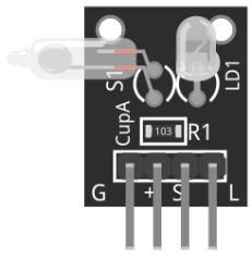
Pin Configuration and Descriptions
The KY-027 module has three pins, as described below:
| Pin | Name | Description |
|---|---|---|
| 1 | VCC | Power supply pin. Connect to 3.3V or 5V. |
| 2 | GND | Ground pin. Connect to the ground of the circuit. |
| 3 | OUT | Output pin. Provides an analog voltage proportional to sound levels or a digital |
| signal based on the threshold set by the onboard potentiometer. |
Usage Instructions
How to Use the KY-027 in a Circuit
- Power the Module: Connect the VCC pin to a 3.3V or 5V power source and the GND pin to the ground.
- Connect the Output:
- For analog sound level detection, connect the
OUTpin to an analog input pin of your microcontroller. - For digital sound detection, adjust the onboard potentiometer to set the desired sound threshold. The
OUTpin will output HIGH when the sound level exceeds the threshold.
- For analog sound level detection, connect the
- Read the Output:
- Use an analog-to-digital converter (ADC) to read the analog output.
- For digital output, monitor the HIGH/LOW state of the
OUTpin.
Important Considerations and Best Practices
- Power Supply: Ensure a stable power supply to avoid noise in the output signal.
- Potentiometer Adjustment: Use the onboard potentiometer to fine-tune the sensitivity of the digital output.
- Placement: Place the module in an area free from excessive vibrations or electrical noise for accurate sound detection.
- Analog vs. Digital Output: Use the analog output for precise sound level measurements and the digital output for simple threshold-based detection.
Example: Connecting KY-027 to Arduino UNO
Below is an example of how to connect and use the KY-027 with an Arduino UNO to read both analog and digital outputs.
Circuit Diagram
- Connect
VCCto the 5V pin on the Arduino. - Connect
GNDto the GND pin on the Arduino. - Connect
OUTto both an analog input pin (e.g., A0) and a digital input pin (e.g., D2).
Arduino Code
// Define pin connections
const int analogPin = A0;  // Analog pin connected to KY-027 OUT
const int digitalPin = 2;  // Digital pin connected to KY-027 OUT

void setup() {
  Serial.begin(9600);  // Initialize serial communication
  pinMode(digitalPin, INPUT);  // Set digital pin as input
}

void loop() {
  // Read analog output from KY-027
  int soundLevel = analogRead(analogPin);
  Serial.print("Analog Sound Level: ");
  Serial.println(soundLevel);

  // Read digital output from KY-027
  int soundDetected = digitalRead(digitalPin);
  if (soundDetected == HIGH) {
    Serial.println("Sound detected (Digital Output HIGH)");
  } else {
    Serial.println("No sound detected (Digital Output LOW)");
  }

  delay(500);  // Wait for 500ms before the next reading
}
Troubleshooting and FAQs
Common Issues and Solutions
No Output from the Module:
- Ensure the module is powered correctly (check VCC and GND connections).
- Verify that the microphone is not damaged.
- Check the potentiometer setting; it may need adjustment.
Inconsistent Analog Readings:
- Ensure the power supply is stable and free from noise.
- Avoid placing the module near sources of electrical interference.
Digital Output Always HIGH or LOW:
- Adjust the potentiometer to set an appropriate sound threshold.
- Verify that the sound level exceeds the set threshold for HIGH output.
FAQs
Q: Can the KY-027 detect specific frequencies of sound?
A: No, the KY-027 is designed to detect general sound levels and does not differentiate between specific frequencies.
Q: How do I increase the sensitivity of the module?
A: Adjust the onboard potentiometer to increase the sensitivity of the digital output. For analog output, ensure the microphone is positioned closer to the sound source.
Q: Can I use the KY-027 with a 3.3V microcontroller?
A: Yes, the KY-027 operates at both 3.3V and 5V, making it compatible with most microcontrollers.
Q: What is the range of sound levels the KY-027 can detect?
A: The KY-027 can detect a wide range of sound levels, but its sensitivity depends on the microphone and the potentiometer setting. It is suitable for general sound detection rather than precise measurements.