How to Use LN298 Motor Controller: Examples, Pinouts, and Specs
Introduction
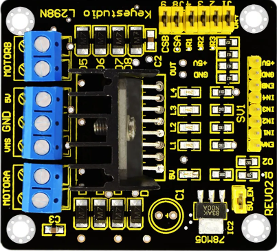
The LN298 Motor Controller is a dual H-bridge motor driver that allows for the control of the speed and direction of two DC motors or one stepper motor. It is designed to handle high current and voltage, making it an ideal choice for various robotics and automation projects. This versatile component is widely used in applications such as robotic arms, conveyor belts, and automated vehicles.
Explore Projects Built with LN298 Motor Controller

Explore Projects Built with LN298 Motor Controller
Technical Specifications
Key Technical Details
| Parameter | Value |
|---|---|
| Operating Voltage | 5V to 46V |
| Output Current | 2A per channel (continuous) |
| Peak Output Current | 3A per channel |
| Logic Voltage | 5V |
| Control Logic | TTL compatible |
| Power Dissipation | 25W |
| Operating Temperature | -25°C to +130°C |
Pin Configuration and Descriptions
| Pin Number | Pin Name | Description |
|---|---|---|
| 1 | Enable A | Enables Motor A (active high) |
| 2 | Input 1 | Motor A input 1 |
| 3 | Input 2 | Motor A input 2 |
| 4 | Ground | Ground |
| 5 | Vcc | Supply voltage for the logic circuitry (5V) |
| 6 | Output 1 | Motor A output 1 |
| 7 | Output 2 | Motor A output 2 |
| 8 | Vss | Supply voltage for the motor (up to 46V) |
| 9 | Output 3 | Motor B output 1 |
| 10 | Output 4 | Motor B output 2 |
| 11 | Ground | Ground |
| 12 | Input 3 | Motor B input 1 |
| 13 | Input 4 | Motor B input 2 |
| 14 | Enable B | Enables Motor B (active high) |
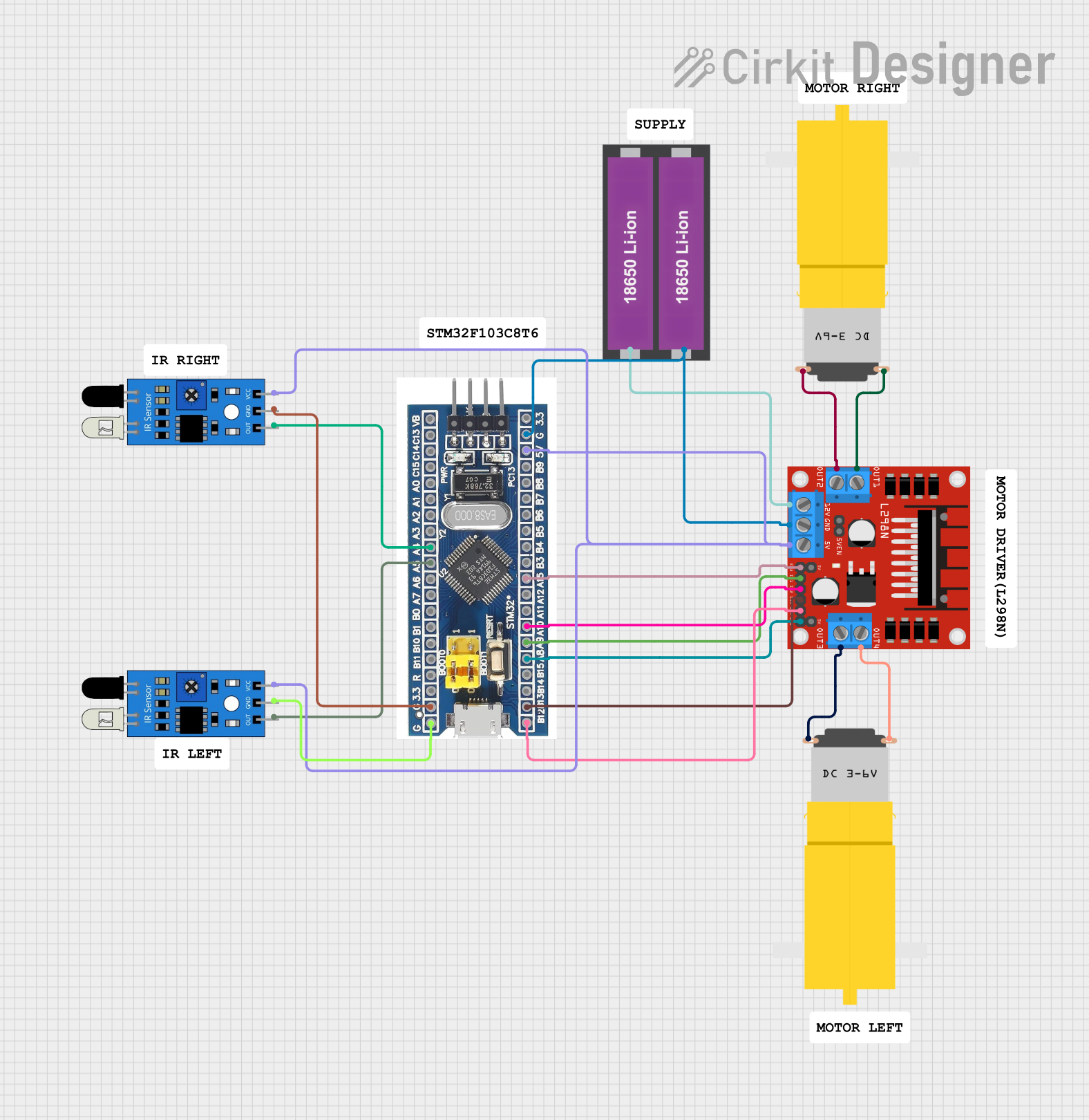
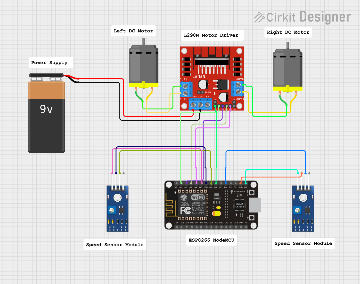
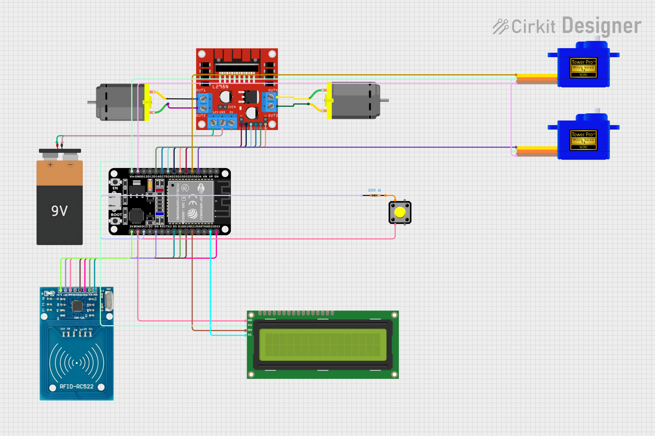
Usage Instructions
How to Use the LN298 Motor Controller in a Circuit
Power Connections:
- Connect the
Vccpin to a 5V power supply. - Connect the
Vsspin to the motor power supply (up to 46V). - Connect the
Groundpins to the ground of the power supply.
- Connect the
Motor Connections:
- Connect the motor terminals to the
Outputpins (1 and 2 for Motor A, 3 and 4 for Motor B).
- Connect the motor terminals to the
Control Connections:
- Connect the
Enablepins to a digital output pin of the microcontroller (e.g., Arduino). - Connect the
Inputpins to digital output pins of the microcontroller to control the direction and speed.
- Connect the
Important Considerations and Best Practices
- Heat Dissipation: The LN298 can dissipate a significant amount of power, so ensure proper heat sinking or cooling to prevent overheating.
- Current Limiting: Use current limiting resistors or a current sensor to protect the motors and the driver from overcurrent conditions.
- Decoupling Capacitors: Place decoupling capacitors close to the power supply pins to filter out noise and stabilize the voltage.
Example Arduino Code
// Define motor control pins
const int enableA = 9;
const int input1 = 8;
const int input2 = 7;
const int enableB = 10;
const int input3 = 6;
const int input4 = 5;

void setup() {
  // Set control pins as outputs
  pinMode(enableA, OUTPUT);
  pinMode(input1, OUTPUT);
  pinMode(input2, OUTPUT);
  pinMode(enableB, OUTPUT);
  pinMode(input3, OUTPUT);
  pinMode(input4, OUTPUT);
}

void loop() {
  // Motor A forward
  digitalWrite(enableA, HIGH);
  digitalWrite(input1, HIGH);
  digitalWrite(input2, LOW);

  // Motor B backward
  digitalWrite(enableB, HIGH);
  digitalWrite(input3, LOW);
  digitalWrite(input4, HIGH);

  delay(2000); // Run motors for 2 seconds

  // Stop motors
  digitalWrite(enableA, LOW);
  digitalWrite(enableB, LOW);

  delay(2000); // Wait for 2 seconds
}
Troubleshooting and FAQs
Common Issues
Motor Not Running:
- Solution: Check the power connections and ensure that the
Enablepins are set high.
- Solution: Check the power connections and ensure that the
Motor Running in Wrong Direction:
- Solution: Verify the connections of the
Inputpins and ensure they are set correctly for the desired direction.
- Solution: Verify the connections of the
Overheating:
- Solution: Ensure proper heat sinking and check for overcurrent conditions.
Noisy Operation:
- Solution: Add decoupling capacitors close to the power supply pins and check for loose connections.
FAQs
Q1: Can I control the speed of the motors with the LN298?
- A1: Yes, you can control the speed by using PWM signals on the
Enablepins.
Q2: Can I use the LN298 to drive a stepper motor?
- A2: Yes, the LN298 can drive a stepper motor by controlling the sequence of the
Inputpins.
Q3: What is the maximum voltage the LN298 can handle?
- A3: The LN298 can handle up to 46V on the
Vsspin.
Q4: How do I protect the LN298 from overcurrent?
- A4: Use current limiting resistors or a current sensor to monitor and limit the current.
This documentation provides a comprehensive guide to using the LN298 Motor Controller, ensuring both beginners and experienced users can effectively integrate it into their projects.