How to Use HSS57: Examples, Pinouts, and Specs
Introduction
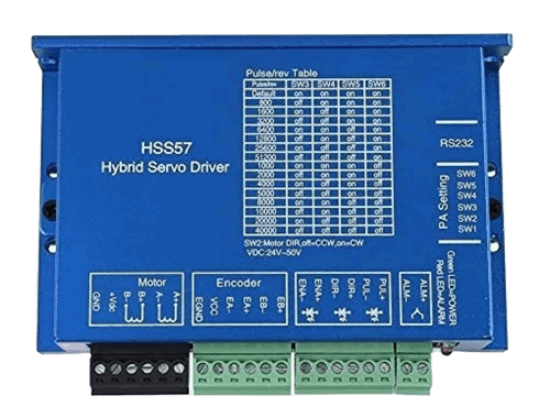
The HSS57 is a high-performance closed-loop stepper motor driver designed for precise motion control applications. Manufactured by Generic, this driver integrates advanced closed-loop control technology to eliminate step loss, improve torque utilization, and enhance overall system efficiency. It is widely used in CNC machines, 3D printers, robotics, and other automation systems requiring accurate and reliable motor control.
Explore Projects Built with HSS57


Explore Projects Built with HSS57
Common Applications and Use Cases
- CNC machinery for precise cutting and milling
- 3D printers for accurate layer deposition
- Robotics for smooth and controlled motion
- Conveyor systems in industrial automation
- Medical devices requiring precise positioning
Technical Specifications
The HSS57 is designed to work with NEMA 23 and NEMA 24 stepper motors, offering a balance of performance and ease of use. Below are the key technical details:
General Specifications
| Parameter | Value |
|---|---|
| Input Voltage Range | 20V to 50V DC |
| Output Current | 0.5A to 5.0A (adjustable) |
| Control Signal Input | Pulse/Direction or CW/CCW |
| Microstepping Resolution | Up to 256 microsteps per step |
| Communication Interface | RS232/RS485 (optional) |
| Operating Temperature | -10°C to +45°C |
| Protection Features | Over-voltage, over-current, |
| and short-circuit protection |
Pin Configuration and Descriptions
The HSS57 driver features a set of input/output terminals for easy integration into your system. Below is the pin configuration:
Power and Motor Connections
| Pin Name | Description |
|---|---|
| V+ | Positive DC power input (20-50V) |
| V- | Negative DC power input (GND) |
| A+ | Motor winding A+ connection |
| A- | Motor winding A- connection |
| B+ | Motor winding B+ connection |
| B- | Motor winding B- connection |
Control Signal Connections
| Pin Name | Description |
|---|---|
| PUL+ | Pulse signal input (positive) |
| PUL- | Pulse signal input (negative) |
| DIR+ | Direction signal input (positive) |
| DIR- | Direction signal input (negative) |
| ENA+ | Enable signal input (positive) |
| ENA- | Enable signal input (negative) |
Usage Instructions
How to Use the HSS57 in a Circuit
- Power Supply: Connect a DC power supply (20-50V) to the V+ and V- terminals. Ensure the power supply can provide sufficient current for your motor.
- Motor Connection: Connect the stepper motor windings to the A+, A-, B+, and B- terminals. Double-check the wiring to avoid damage.
- Control Signals: Connect the PUL, DIR, and ENA pins to your controller (e.g., Arduino, PLC). Use appropriate pull-up or pull-down resistors if required.
- Microstepping Configuration: Set the microstepping resolution using the DIP switches on the driver. Refer to the datasheet for specific switch settings.
- Current Adjustment: Adjust the output current using the potentiometer or DIP switches to match your motor's rated current.
Important Considerations and Best Practices
- Heat Dissipation: Mount the driver on a heat sink or ensure proper ventilation to prevent overheating.
- Signal Integrity: Use shielded cables for control signals to minimize noise interference.
- Power Supply: Use a regulated power supply to avoid voltage fluctuations that could damage the driver.
- Motor Compatibility: Ensure the stepper motor's voltage and current ratings are compatible with the HSS57.
Example: Connecting the HSS57 to an Arduino UNO
Below is an example of how to control the HSS57 using an Arduino UNO:
// Define control pins for the HSS57 driver
const int pulsePin = 2;  // Pulse signal pin
const int dirPin = 3;    // Direction signal pin
const int enaPin = 4;    // Enable signal pin

void setup() {
  // Set control pins as outputs
  pinMode(pulsePin, OUTPUT);
  pinMode(dirPin, OUTPUT);
  pinMode(enaPin, OUTPUT);

  // Enable the driver
  digitalWrite(enaPin, LOW);  // LOW enables the driver
}

void loop() {
  // Set direction
  digitalWrite(dirPin, HIGH);  // HIGH for one direction, LOW for the other

  // Generate pulses to move the motor
  for (int i = 0; i < 200; i++) {  // 200 pulses for one revolution (1.8° step)
    digitalWrite(pulsePin, HIGH);
    delayMicroseconds(500);  // Adjust pulse width for speed control
    digitalWrite(pulsePin, LOW);
    delayMicroseconds(500);
  }

  delay(1000);  // Wait for 1 second before reversing direction

  // Reverse direction
  digitalWrite(dirPin, LOW);
  for (int i = 0; i < 200; i++) {
    digitalWrite(pulsePin, HIGH);
    delayMicroseconds(500);
    digitalWrite(pulsePin, LOW);
    delayMicroseconds(500);
  }

  delay(1000);  // Wait for 1 second before repeating
}
Troubleshooting and FAQs
Common Issues and Solutions
Motor Not Moving:
- Check the power supply voltage and connections.
- Verify the control signal wiring and ensure the controller is sending pulses.
- Ensure the motor windings are connected correctly.
Overheating:
- Ensure proper ventilation or use a heat sink.
- Reduce the output current setting if it exceeds the motor's rated current.
Step Loss or Inconsistent Motion:
- Check for noise interference in the control signals.
- Use shielded cables and proper grounding.
Driver Not Enabling:
- Verify the ENA signal is set to LOW (active state).
- Check for loose or incorrect wiring.
FAQs
Q: Can the HSS57 work with a 12V power supply?
A: No, the minimum input voltage is 20V. Using a 12V supply may result in insufficient torque or damage to the driver.
Q: How do I set the microstepping resolution?
A: Use the DIP switches on the driver. Refer to the datasheet for the specific switch settings corresponding to different resolutions.
Q: Is the HSS57 compatible with NEMA 17 motors?
A: The HSS57 is optimized for NEMA 23 and NEMA 24 motors. It may work with NEMA 17 motors, but performance may vary.
Q: Can I use the HSS57 with a Raspberry Pi?
A: Yes, the HSS57 can be controlled using GPIO pins on a Raspberry Pi. Ensure proper voltage level shifting if required.