How to Use Driver: Examples, Pinouts, and Specs
Introduction
A driver is an electronic component designed to provide the necessary current and voltage to control other components, such as motors, LEDs, or actuators. It acts as an intermediary between a control signal (e.g., from a microcontroller) and the load, ensuring proper operation and performance. Drivers are essential in applications where the control signal alone cannot supply sufficient power to the load.
The DFRobot Driver (Part ID: 1121) is a versatile and reliable solution for driving various components. It is commonly used in robotics, automation systems, LED lighting, and motor control applications.
Explore Projects Built with Driver
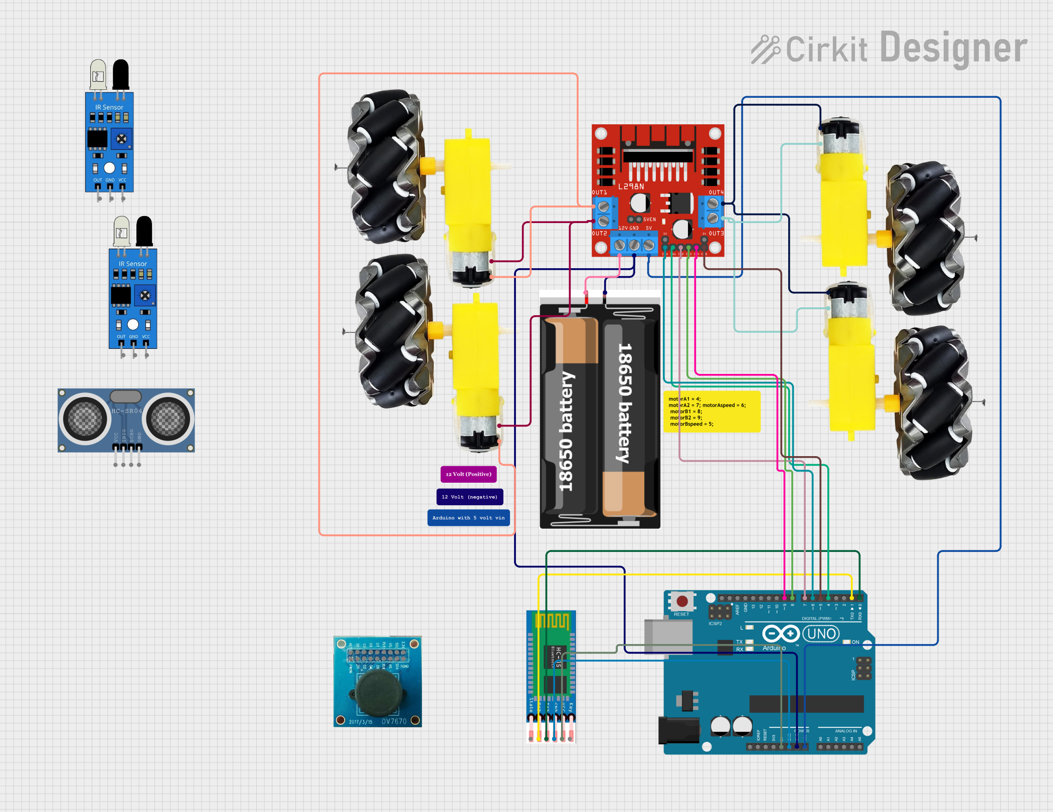
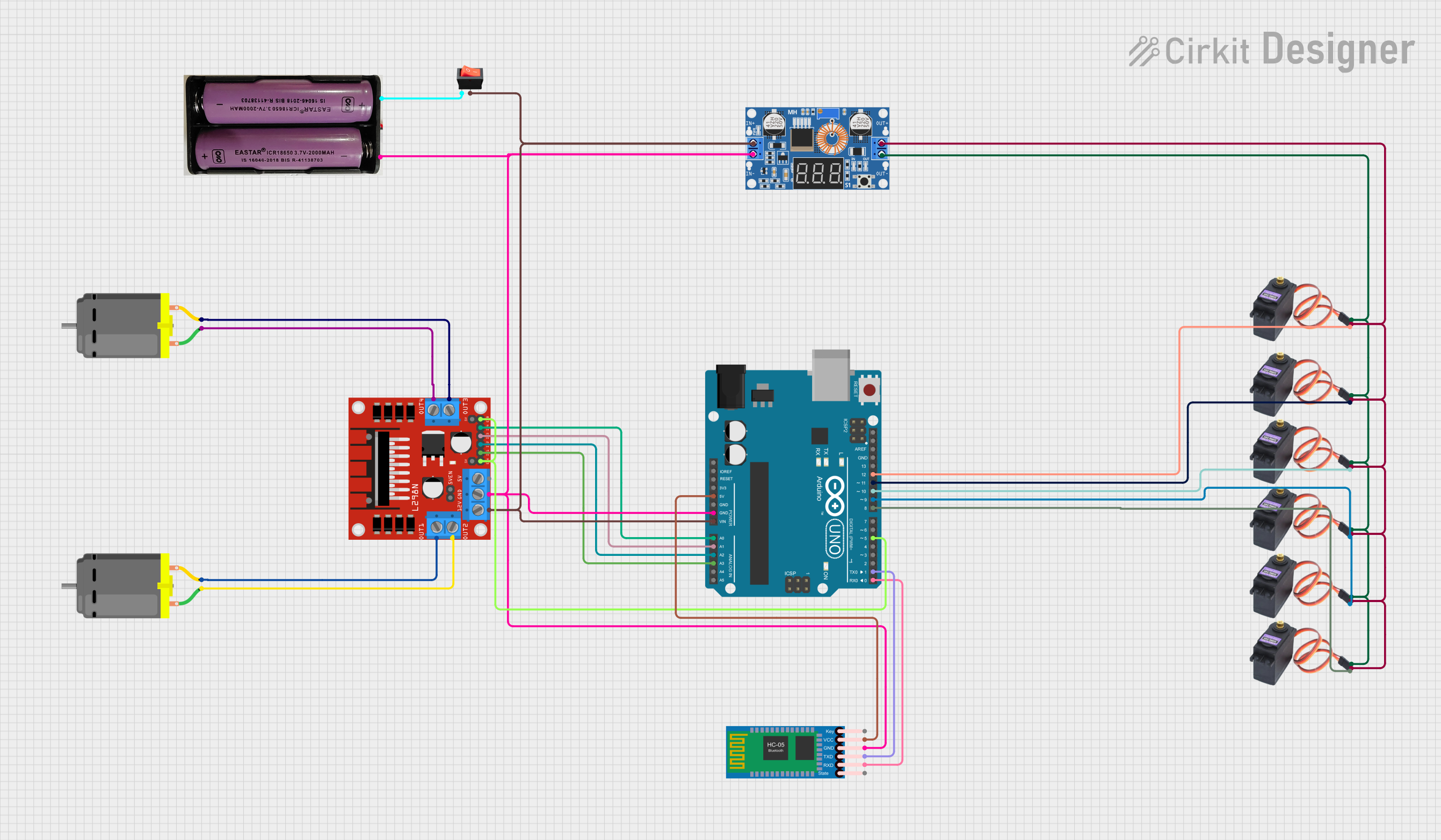
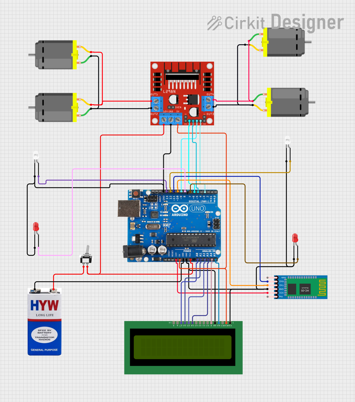
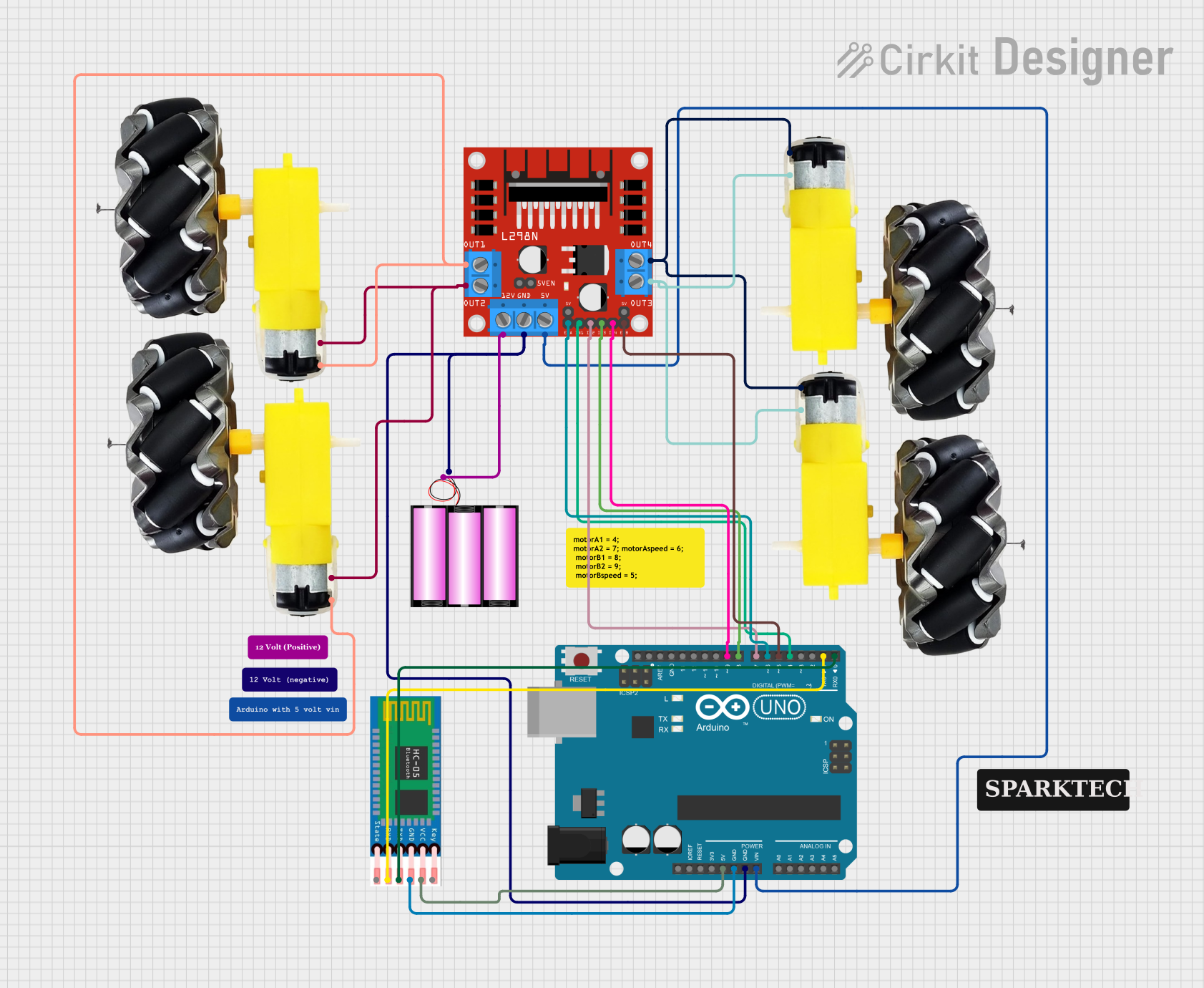
Explore Projects Built with Driver
Technical Specifications
The DFRobot Driver (1121) is designed to handle a wide range of loads while maintaining efficiency and reliability. Below are its key technical specifications:
General Specifications
- Manufacturer: DFRobot
- Part ID: 1121
- Input Voltage Range: 5V to 24V DC
- Output Current: Up to 2A per channel
- Number of Channels: 2 (dual-channel driver)
- Control Signal Voltage: 3.3V or 5V logic compatible
- Operating Temperature: -20°C to 85°C
- Dimensions: 40mm x 30mm x 15mm
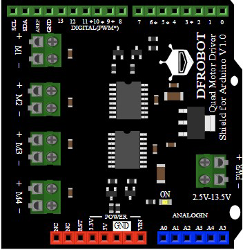
Pin Configuration and Descriptions
The DFRobot Driver (1121) features a simple pinout for easy integration into circuits. Below is the pin configuration:
| Pin Name | Type | Description |
|---|---|---|
| VCC | Power Input | Connect to the positive terminal of the power supply (5V to 24V DC). |
| GND | Power Ground | Connect to the ground terminal of the power supply. |
| IN1 | Control Input | Control signal for Channel 1 (logic HIGH or LOW). |
| IN2 | Control Input | Control signal for Channel 2 (logic HIGH or LOW). |
| OUT1 | Output | Output terminal for Channel 1 (connect to the load, e.g., motor or LED). |
| OUT2 | Output | Output terminal for Channel 2 (connect to the load, e.g., motor or LED). |
| EN | Enable Input | Enable pin for the driver (logic HIGH to enable, LOW to disable both channels). |
Usage Instructions
The DFRobot Driver (1121) is straightforward to use in a variety of circuits. Follow the steps below to integrate it into your project:
Connecting the Driver
- Power Supply: Connect the VCC pin to a DC power source (5V to 24V) and the GND pin to the ground of the power source.
- Control Signals: Connect the IN1 and IN2 pins to the control signals from a microcontroller (e.g., Arduino UNO). Ensure the logic levels are compatible (3.3V or 5V).
- Load Connection: Connect the load (e.g., motor or LED) to the OUT1 and OUT2 pins. Ensure the load's voltage and current requirements are within the driver's specifications.
- Enable Pin: Connect the EN pin to a HIGH signal to enable the driver. If left unconnected, the driver will remain disabled.
Example: Using the Driver with an Arduino UNO
Below is an example of how to use the DFRobot Driver (1121) to control a DC motor with an Arduino UNO:
// Define control pins for the driver
const int enablePin = 9;  // Enable pin for the driver
const int in1Pin = 7;     // Control pin for Channel 1
const int in2Pin = 8;     // Control pin for Channel 2

void setup() {
  // Set pin modes
  pinMode(enablePin, OUTPUT);
  pinMode(in1Pin, OUTPUT);
  pinMode(in2Pin, OUTPUT);

  // Enable the driver
  digitalWrite(enablePin, HIGH);

  // Start the motor in forward direction
  digitalWrite(in1Pin, HIGH);  // Set IN1 HIGH
  digitalWrite(in2Pin, LOW);   // Set IN2 LOW
}

void loop() {
  // Run the motor forward for 5 seconds
  delay(5000);

  // Stop the motor
  digitalWrite(in1Pin, LOW);
  digitalWrite(in2Pin, LOW);
  delay(2000);

  // Run the motor in reverse for 5 seconds
  digitalWrite(in1Pin, LOW);
  digitalWrite(in2Pin, HIGH);
  delay(5000);

  // Stop the motor
  digitalWrite(in1Pin, LOW);
  digitalWrite(in2Pin, LOW);
  delay(2000);
}
Important Considerations
- Ensure the power supply voltage matches the requirements of both the driver and the load.
- Do not exceed the maximum current rating (2A per channel) to avoid damaging the driver.
- Use appropriate heat dissipation methods if the driver operates at high currents for extended periods.
- Always connect the GND of the driver to the GND of the control circuit (e.g., Arduino) to ensure proper operation.
Troubleshooting and FAQs
Common Issues and Solutions
Driver Not Responding to Control Signals
- Cause: The EN pin is not connected or set to LOW.
- Solution: Ensure the EN pin is connected to a HIGH signal to enable the driver.
Load Not Operating Properly
- Cause: Insufficient power supply or incorrect wiring.
- Solution: Verify the power supply voltage and current are adequate for the load. Double-check all connections.
Driver Overheating
- Cause: Excessive current draw or poor ventilation.
- Solution: Ensure the load does not exceed the driver's current rating. Use a heatsink or fan if necessary.
Control Signals Not Working
- Cause: Logic level mismatch between the microcontroller and the driver.
- Solution: Confirm that the control signals are 3.3V or 5V logic compatible.
FAQs
Q1: Can the driver control two different loads simultaneously?
A1: Yes, the DFRobot Driver (1121) has two independent channels, allowing you to control two separate loads.
Q2: Is the driver compatible with PWM signals?
A2: Yes, the driver supports PWM signals for speed or brightness control of motors and LEDs.
Q3: What happens if the load exceeds the current rating?
A3: Exceeding the current rating may damage the driver. Always ensure the load's current requirements are within the specified limits.
Q4: Can I use the driver with a 3.3V microcontroller?
A4: Yes, the driver is compatible with both 3.3V and 5V logic levels.