How to Use MT6835 Encoder: Examples, Pinouts, and Specs
Introduction
The MT6835 Encoder is a high-performance device designed to convert analog signals into digital data. It is widely used in applications such as audio processing, video encoding, and data transmission. This encoder is known for its precision, reliability, and versatility, making it a popular choice in both consumer and industrial electronics.
Explore Projects Built with MT6835 Encoder


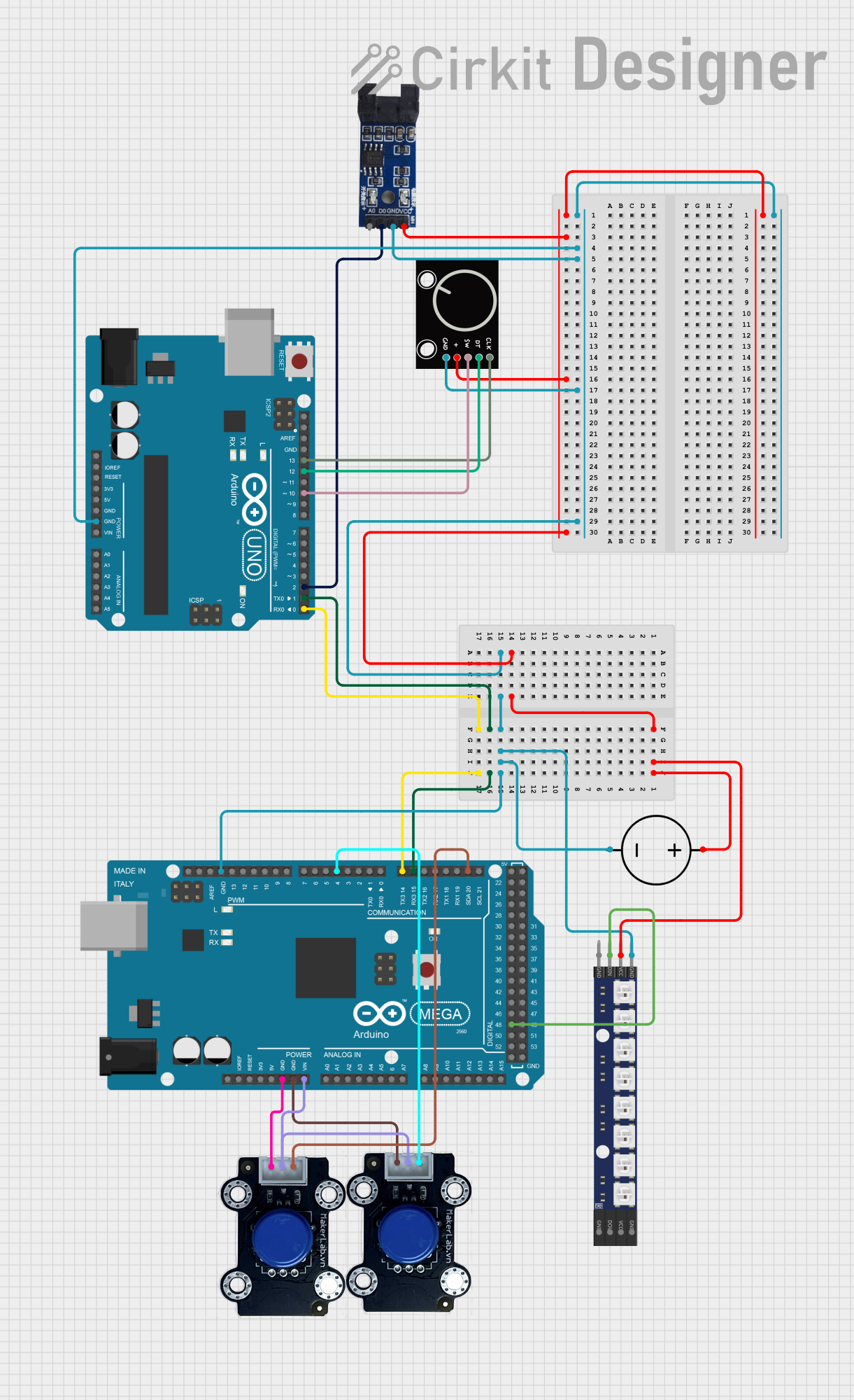
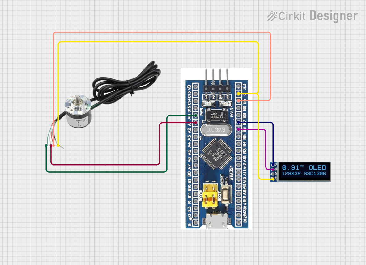
Explore Projects Built with MT6835 Encoder
Common Applications and Use Cases
- Audio signal processing for high-fidelity sound systems
- Video encoding in surveillance and broadcasting systems
- Data acquisition and transmission in industrial automation
- Robotics and motor control systems requiring precise signal conversion
- Medical devices for signal monitoring and analysis
Technical Specifications
The MT6835 Encoder is engineered to deliver robust performance under a variety of conditions. Below are its key technical specifications:
General Specifications
| Parameter | Value |
|---|---|
| Supply Voltage (Vcc) | 3.3V to 5.5V |
| Operating Temperature | -40°C to +125°C |
| Resolution | 12-bit to 16-bit |
| Output Format | SPI, PWM, or Quadrature |
| Maximum Sampling Rate | 10 kHz |
| Power Consumption | < 10 mA at 5V |
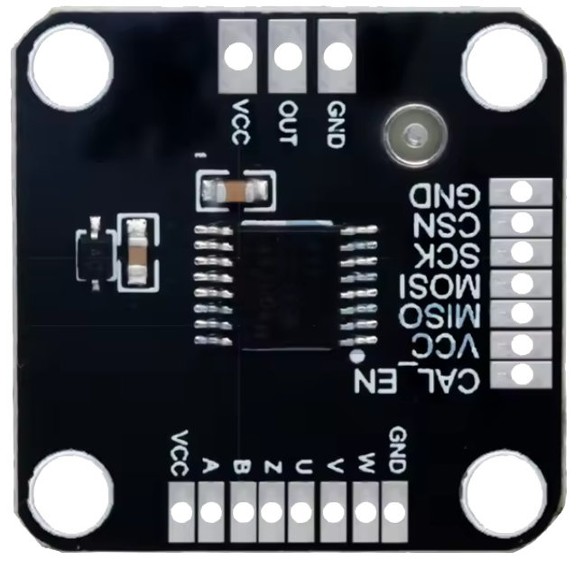
Pin Configuration and Descriptions
The MT6835 Encoder typically comes in a compact 8-pin package. Below is the pinout and description:
| Pin Number | Pin Name | Description |
|---|---|---|
| 1 | VCC | Power supply input (3.3V to 5.5V) |
| 2 | GND | Ground connection |
| 3 | AOUT | Analog signal input |
| 4 | SCK | Serial Clock input for SPI communication |
| 5 | MISO | Master In Slave Out - SPI data output |
| 6 | PWM_OUT | Pulse Width Modulation output for digital signal representation |
| 7 | CS | Chip Select input for SPI communication |
| 8 | NC | No connection (reserved for future use or left unconnected) |
Usage Instructions
The MT6835 Encoder is straightforward to integrate into a circuit. Below are the steps and best practices for using this component effectively:
How to Use the MT6835 Encoder in a Circuit
- Power Supply: Connect the VCC pin to a stable 3.3V or 5V power source and the GND pin to the ground.
- Signal Input: Feed the analog signal to the AOUT pin. Ensure the input signal is within the acceptable range to avoid damage.
- Communication Interface:
- For SPI communication, connect the SCK, MISO, and CS pins to the corresponding pins on your microcontroller.
- For PWM output, connect the PWM_OUT pin to the desired digital input pin of your microcontroller.
- Bypass Capacitor: Place a 0.1 µF ceramic capacitor close to the VCC and GND pins to filter noise and ensure stable operation.
- Programming: If using an Arduino UNO, configure the SPI or PWM interface in your code to read the digital output from the encoder.
Important Considerations and Best Practices
- Signal Integrity: Use shielded cables for the analog input to minimize noise interference.
- Voltage Levels: Ensure the power supply and signal levels are within the specified range to prevent damage.
- Sampling Rate: Adjust the sampling rate based on your application requirements to balance precision and speed.
- Heat Dissipation: Operate the encoder within the recommended temperature range to avoid overheating.
Example Code for Arduino UNO (SPI Communication)
#include <SPI.h>

// Define SPI pins for the MT6835 Encoder
const int CS_PIN = 10; // Chip Select pin

void setup() {
  Serial.begin(9600); // Initialize serial communication for debugging
  pinMode(CS_PIN, OUTPUT); // Set CS pin as output
  digitalWrite(CS_PIN, HIGH); // Set CS pin high (inactive)

  SPI.begin(); // Initialize SPI communication
  SPI.setClockDivider(SPI_CLOCK_DIV16); // Set SPI clock speed
  SPI.setDataMode(SPI_MODE0); // Set SPI mode
}

void loop() {
  digitalWrite(CS_PIN, LOW); // Activate the encoder by pulling CS low
  delayMicroseconds(10); // Small delay for stability

  // Read data from the encoder
  byte highByte = SPI.transfer(0x00); // Send dummy byte to receive high byte
  byte lowByte = SPI.transfer(0x00);  // Send dummy byte to receive low byte
  digitalWrite(CS_PIN, HIGH); // Deactivate the encoder by pulling CS high

  // Combine high and low bytes into a 16-bit value
  int encoderValue = (highByte << 8) | lowByte;

  // Print the encoder value to the serial monitor
  Serial.print("Encoder Value: ");
  Serial.println(encoderValue);

  delay(100); // Wait before the next reading
}
Troubleshooting and FAQs
Common Issues and Solutions
No Output Signal:
- Cause: Incorrect power supply or loose connections.
- Solution: Verify the VCC and GND connections and ensure the power supply is within the specified range.
Erratic or Noisy Output:
- Cause: Noise interference or improper grounding.
- Solution: Use shielded cables for the analog input and ensure a proper ground connection.
Incorrect Data from SPI:
- Cause: Mismatched SPI settings or incorrect wiring.
- Solution: Double-check the SPI mode, clock speed, and pin connections.
Overheating:
- Cause: Operating outside the recommended temperature range.
- Solution: Ensure adequate ventilation and avoid exposure to high temperatures.
FAQs
Q1: Can the MT6835 Encoder handle multiple input signals?
A1: No, the MT6835 Encoder is designed to process a single analog input signal at a time.
Q2: What is the maximum cable length for the analog input?
A2: The maximum cable length depends on the signal quality and shielding. For best results, keep the cable length under 1 meter.
Q3: Can I use the MT6835 Encoder with a 3.3V microcontroller?
A3: Yes, the MT6835 Encoder supports a supply voltage range of 3.3V to 5.5V, making it compatible with 3.3V microcontrollers.
Q4: Is the MT6835 Encoder suitable for high-frequency signals?
A4: The encoder supports a maximum sampling rate of 10 kHz, so it is suitable for low to mid-frequency signals.